|
When people are introduced one of my automata pieces they always ask, "How does it work? How do you figure it out?" This blog entry will take a stab at answering a bit of both questions. Lets take our character below, Otto Mata, and have him raise his hand to wave at his adoring public! To make Otto's hand, (Point A) rise in a waving gesture 1-1/4", (distance "a" in the diagram) how much do we need to cut into cam G. This amount will be distance "g" in the diagram, the difference between the minimum and maximum cam diameter. The answer lies in understanding the length of the levers and fulcrums that are part of the linkages between these to points. I'll perform the calculation with the arm in the neutral, position, that is half way up. There are minor corrections that can be applied for fact that many points are following arcs not straight lines, but they will be ignored in this example. 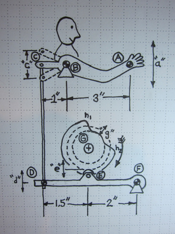 Since Point B is fixed on Otto's shoulder and only allowed to rotate, Point C will move down as Point A moves up. It will move in portion to the leverage around the fulcrum at Point B. For Point A to rise 1.25", Point C must move 1.25" x 1/3 = 0.4167" downward.
Point D on the cam follower will travel the same distance since C and D are pinned connections (i.e. distance "c" = "d"). Since the end of the follower, Point F, can only rotate, the amount Point E will move is also a function of the lever length. Because the two points are on the same side of the fulcrum at F, the calculation to determine the distance "e" is a little different that the previous one. Point E will move (0.4167" x 2/(1.5 +2)) = .238" Translating this to the cam means that the difference between the minimum and maximum diameter on the cam must be 0.238", slightly less than 1/4" If the nominal diameter of the cam was to be 2" then the cam should have a (2+0.238/2) = 2.129" outside diameter, and a diameter of (2-0.238/2) = 1.88" where the arm is to be raised. How fast Otto's arm rises and falls, and how long it stays up is a whole other story! Who knows, it could be a future blog posting.
4 Comments
Hopefully I have put the last of the details on Billy the fishing boy. All the mechanical linkages have been test fitted for the upper characters. You may see the follower for the eye movement and shaft to turn Billy's head inside the glass on the right side. On the left is the follower to make his right arm rise and fall. His left arm is attached to the dock. It moves side to side. There has been a lot more fitting of this piece than expected. In an effort to keep things compact in the piece I have not left much room for error, let alone fat fingers. P.S. The shoes are Converse, like the ones I had as a kid. 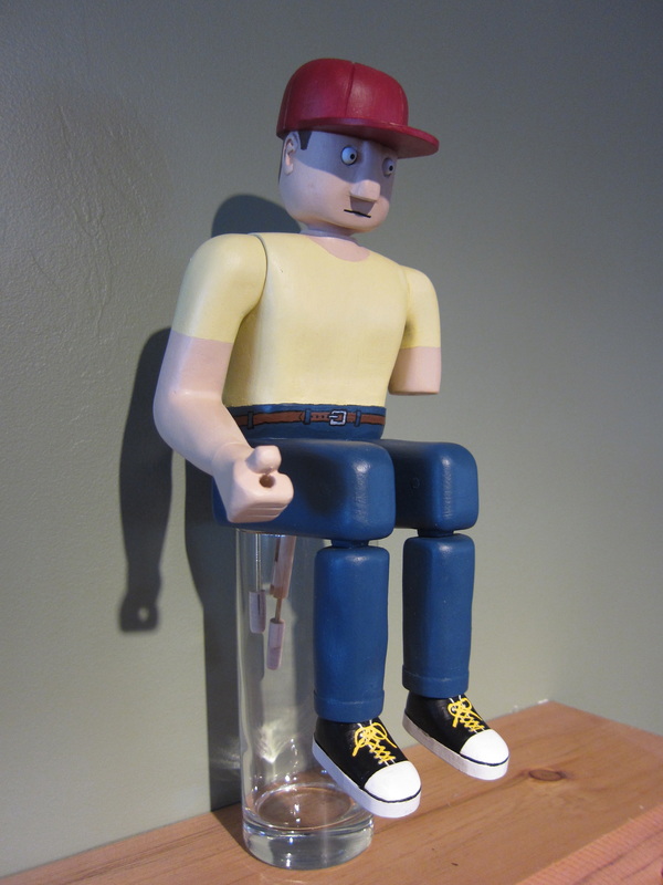
Getting around to the final assembly after cutting a new case for the automata. Unfortunately the new box was not quite an exact replica of the previous one so some adjustments were needed. There is likely a lesson learned here! As a result I have had to add a few 1/32" shims under a few of the pedestals to make the mechanism run freely. You can see one of them being fitted under the centre pedestal in the photo. 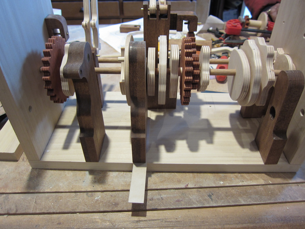
No shop time this week, so there is not much new to show you. when I was last at work I was tuning up all the mechanism actions, adding counter weights and linkages in the prototype before I moved the guts into the final case. Its getting a little crowded in a couple of areas, in particular in the area where Bigmouth the bass resides. But I think things are getting worked out. I'll be back at it on Saturday! 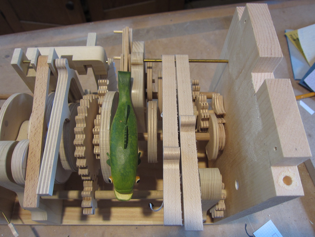
After working on numerous other little bits I finally got to point where I could determine how long the neck shaft should be so I completed the head mechanism discussed a few blogs ago. The photo below follows up from the last series showing how the eyeball axles get glued into the head. Not the best looking glue job, but it works, and the only ones seeing it will be me and those reading this blog! The key here is to not get glue onto the eyeballs so they will still move. 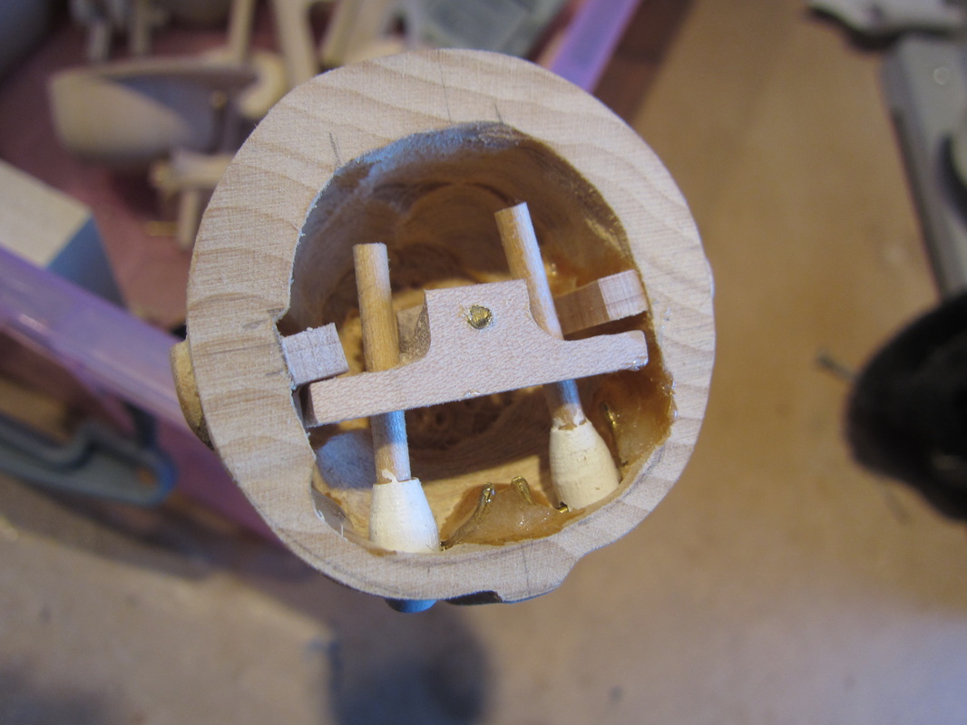
Here's another view showing things in place and the eyeball in the full down (rod up) position. 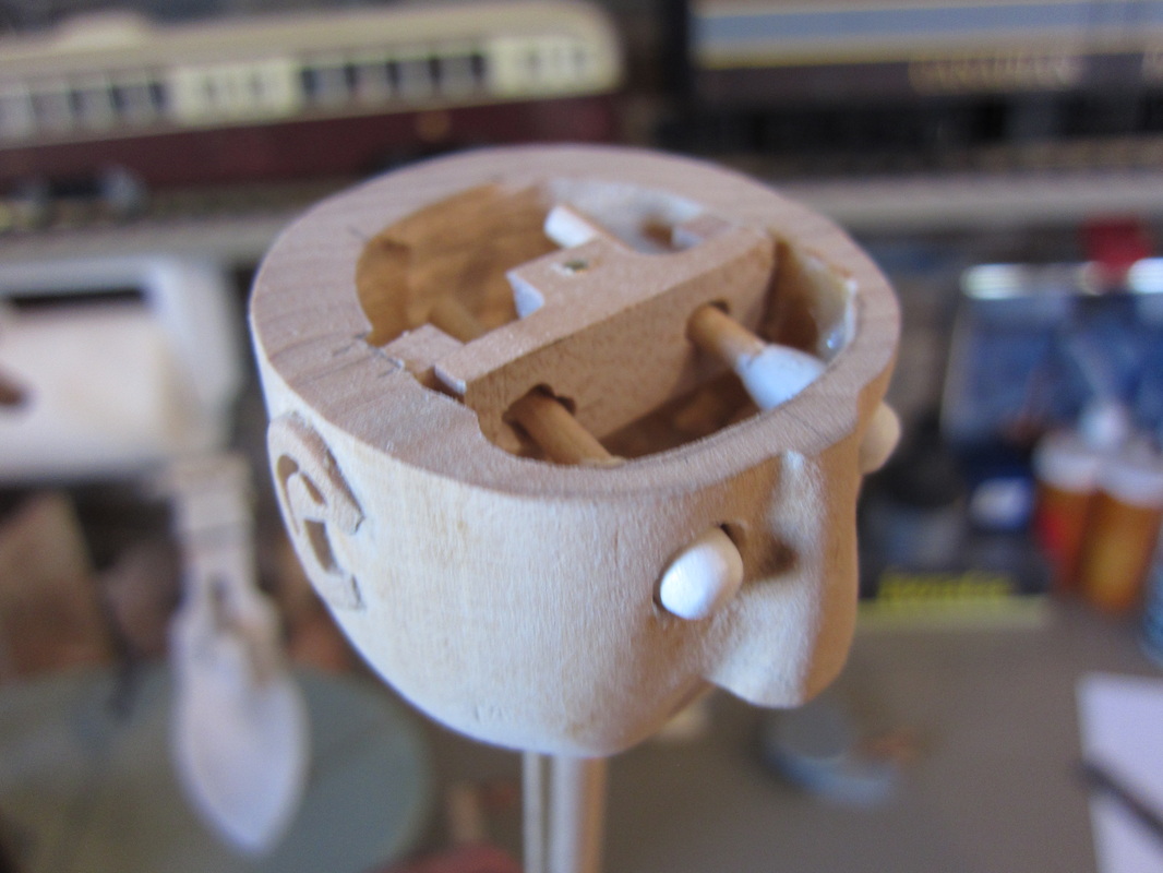
The last step is to glue on the hat hiding the inside mechanism for good. A couple pupils should bring him to life. Alternately a hole cut in the back of the head can be filled in and disguised in hair details. Now what logo to put on the hat! 
The eyes are made from dowels, in this case 1/4", and have smaller 1/8" dowels glued into the back. These small dowels will fit through the sliding plate to impart movement to the eyeballs. I paint the eyeball white before assembly as it is easier than painting later. 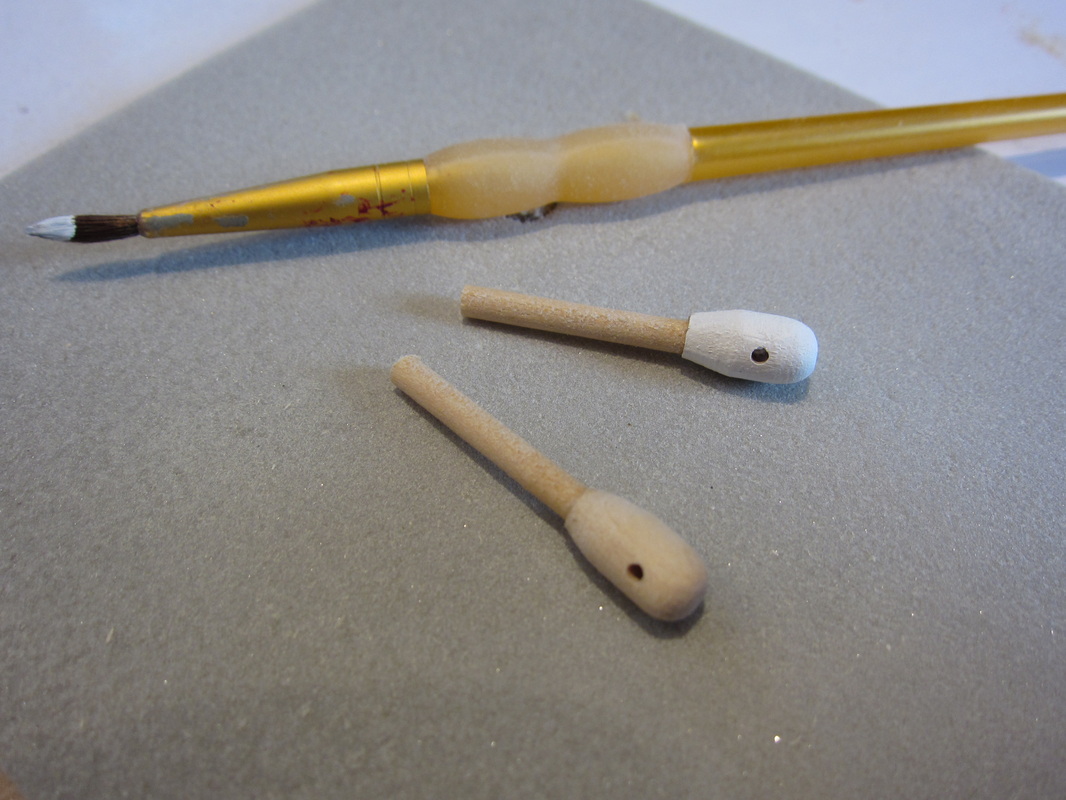
The actuator for the eyes runs up on the inside of a 3/8" dowel. The dowel is glued into the base of the neck and is used to turn the head. I glue spacers in the dowel to keep the rod in the centre and strengthen the dowel. 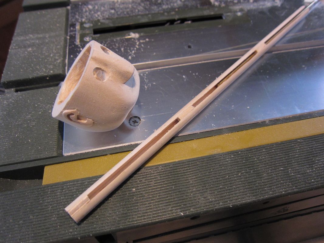
Here is the sliding plate affixed to the top of the control rod. The control piece is made of hardwood (maple) and the is a 4-40 tapped thread is cut into the hole which the brass rod is threaded into. The assembly will be coated in CA glue when finally assembled. The holes have to be loose fitting to account for the movement of the rod. Diagonal slots make the eyes move side to side, vertical up and down. 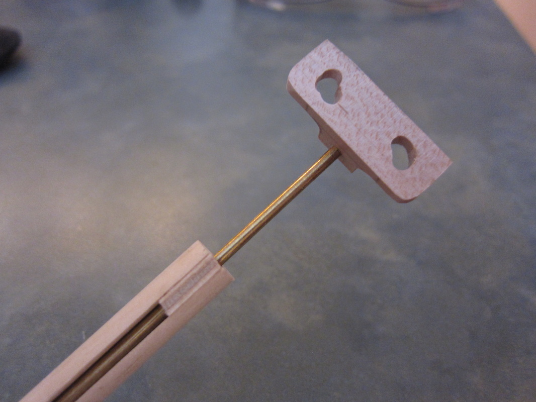
Here is the assembly in place. The brass rods used for axles of the eyeballs will be epoxied into grooves carefully cut into the inside of the head. By moving the slider up and down the eyes will them pivot of the rods. A pupil painted on the eye ball will then appear to look up and down. The top of the head will be glued on and access to the head internals will be eliminated. 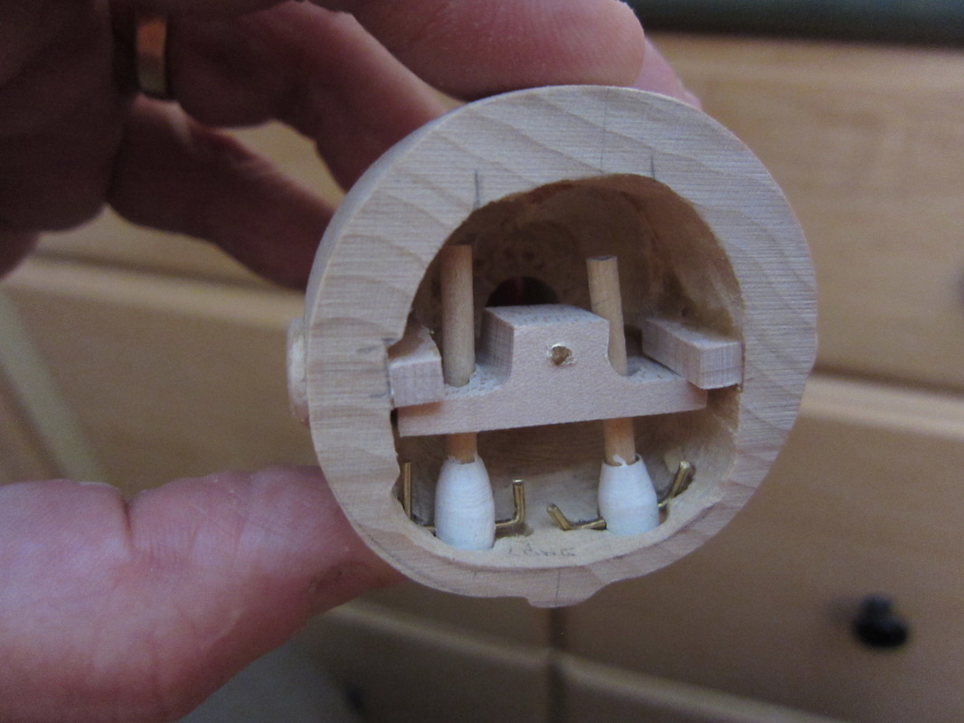
The eye sockets must be shaped carefully as the wood here needs to be fairly thin. The sockets need slight elongation up and down to allow full movement of the dowels. Cutting the grooves for the axles requires a steady hand, but with practice it is all possible! I'lll post detail of the head when completed.
A Given a little hole, sometimes you just have to fill it! I decided to add another leviathan under the dock of the current automata construction. This time I chose to add a catfish. He will not move in an out like the other fish I have made, but will lurk under the dock opening and closing his mouth. He is about 4 " long, 3/4" tall in the body and 1-1/4" wide. I started with a piece of basswood and cut, carved, and sanded the shape as shown below. The smaller piece in the photo is the lower jaw. 
In order to actuate the lower jaw I am using a 1/16" brass rod running up from behind inside the catfish. I placed a 1/8" hollow tube so it would slide easily. In the photo below you can see through the fish's mouth into a 1/4" hole and eventually into the tube. The 1/4" hole is to allow some freedom of movement for the brass rod. The mouth of the fish was hollowed out with a carbide bit on a Dremel tool. 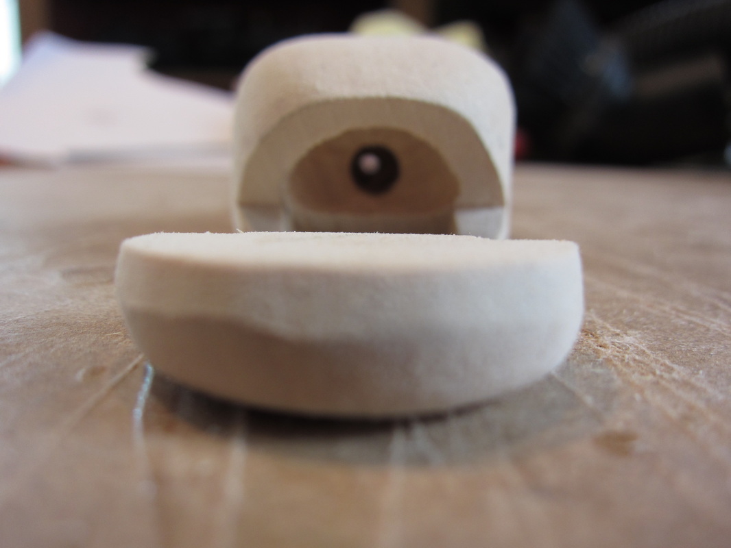
Whiskers were added using 3/32" brass rod. In these photos they have not been cut to finished length. Fins have been added but I have yet to use my wood burner to add detail to them. I wanted the catfish to look a little "scary" when I designed him, but somehow he ended up looking a little like a Grouper in serious need of a shave. The good thing about automata is that you can always say that this fish was meant to be whimsical in the first place. He is mounted on a block which will secure him to the automata case. 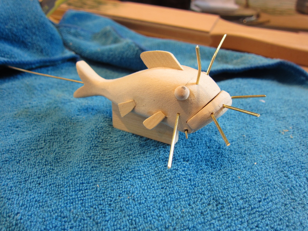
A new feature of my web provider is that I can now add short video segments into the blog, so I added 6 seconds of video showing the catfish in operation to try it out. Till next time. I still have some followup to the head construction to come.
Al I 've started the finishing work on the head of the main character in my current automata. The head will turn to look in either direction and the eyes will look up and down. I learned how to construct the head by following tips from Philip Lowndes' blog. HIs current site is lowbot.co.uk. In this case, since it is in character with the subject, I added a hat which allows me to easily access the interior of the head to build the eye movement mechanism. Here is the head and hat as prepared before the onset of shaping. A little robotic looking I must admit. 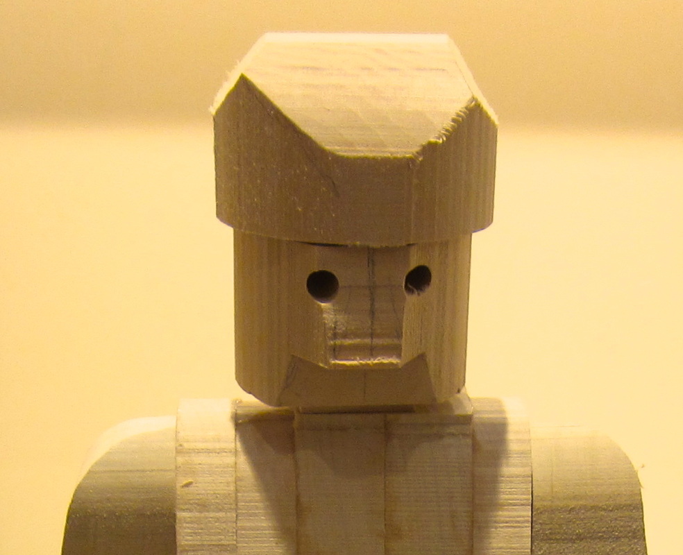 While surfaces are still square is the time to create the hollow in the top of the head. In this case I used a 1/2" forsner bit to eat out the first cavity. 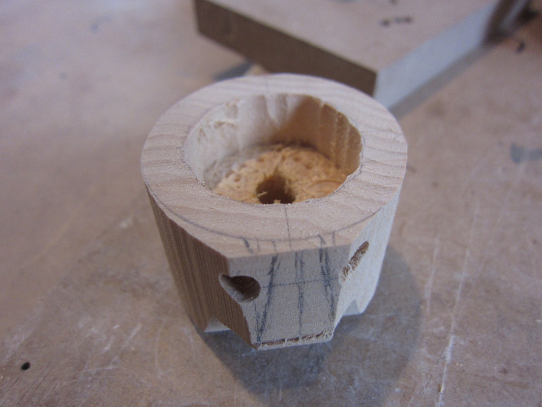 It is time to rough in the face before enlarging the internal cavity. Here is the first pass of the face. Notice the neck has not been shaped yet. 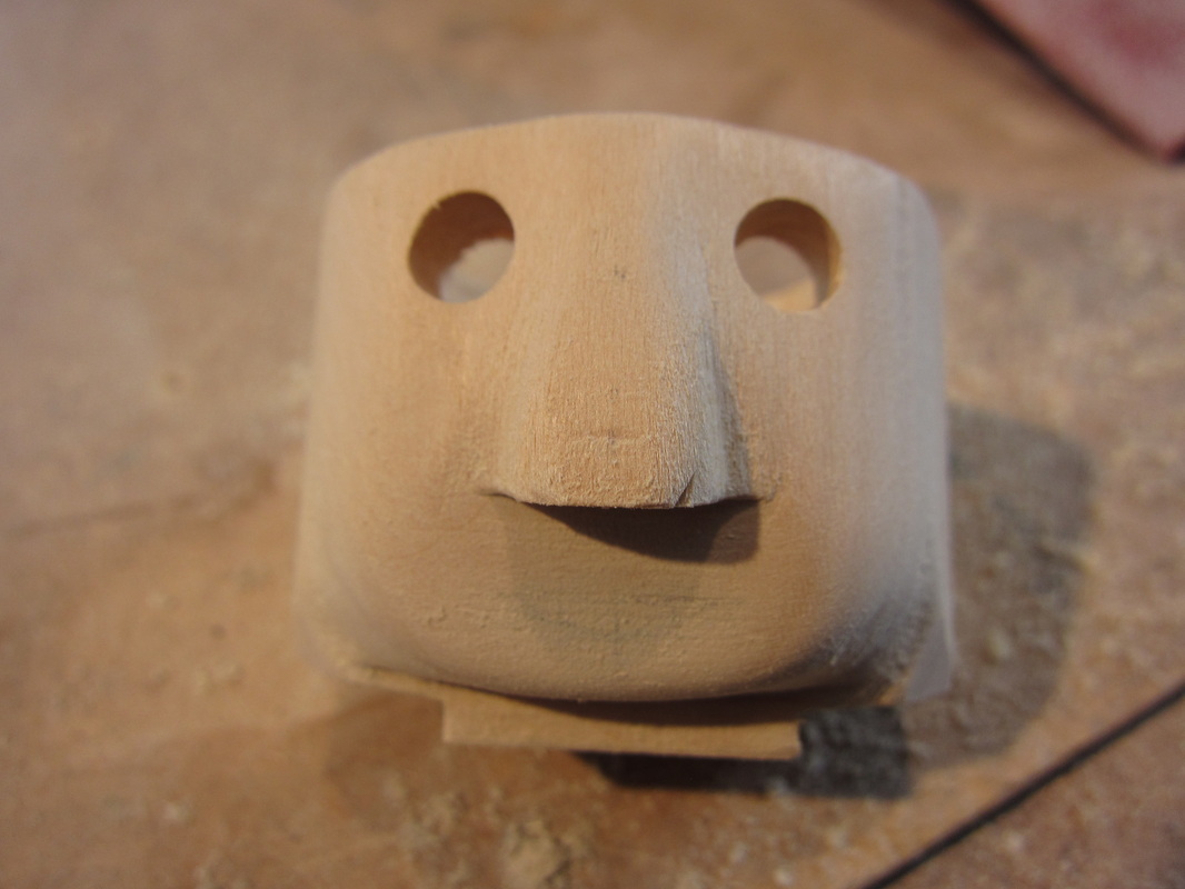 A second round of drilling has deepened the head cavity and some material has been removed behind the eyes in preparation for the coming installation of the eyeballs. Some material has also been removed from inside the hat (left) to allow more range to the eye movement. The arrow is a mark to show the front of the hat dome for alignment with the brim later. 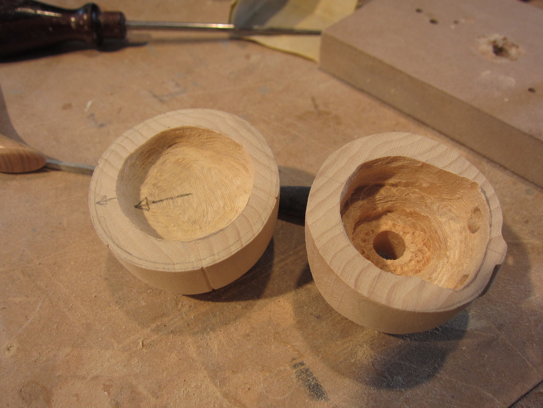 Here is the head inverted showing the neck boss roughed in. 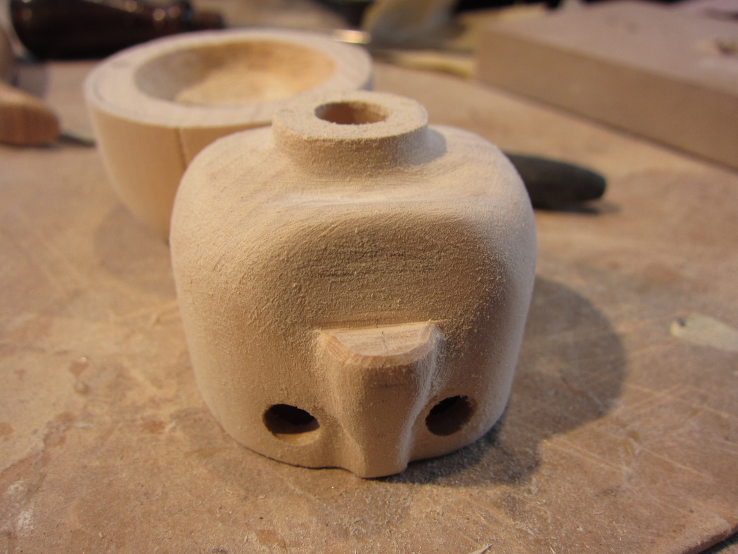 For this piece I cut the ears rather than carve them. After they are glued in place some careful sanding can help them to appear as part of the block that is the head. These ears are about 18mm or a little over 5/8" long. 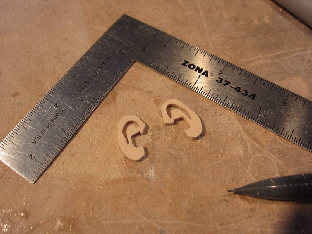 Here is the rough look of the character. The hat is just sitting on his head for the photo. I stuck a couple of dowels in the eyes temporarily because a photo with two empty eye holes looks looks a little spooky. I may rotate the hat, as some as kids wear them today, so the eye movement is more visible. The ears are yet to be shaped. 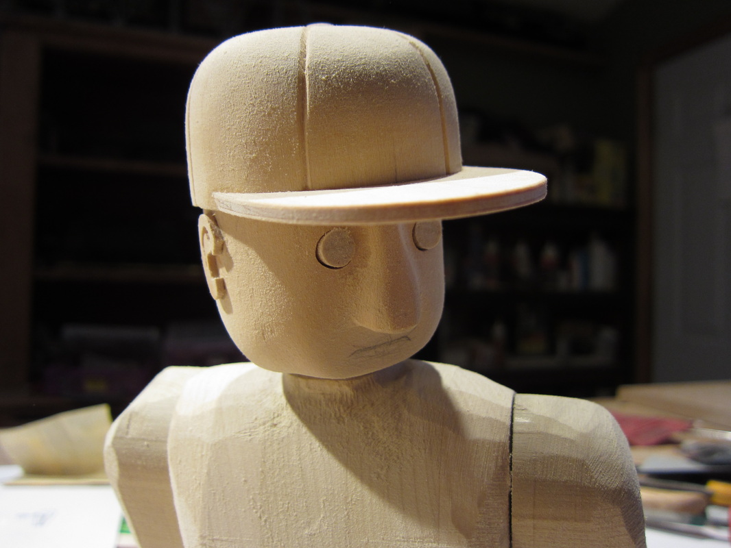 Next job is to build the eyeballs and build internal the mechanism that allows them to move in the head. That's tomorrows job!
Al Took a break for a few days from automata work this week. I was working on a kitchen renovation at my daughter's house. That done it was back to the computer to finish up the design and drawing of the current project. People often ask how I come up with the design and all the little pieces. Some think when they see a finished piece it must of come in a kit! I consider this a sad reflection on todays consumerism standards. Even worse it might suggest that I look to dense to have figured it out myself! So here is a view of the CAD design of the current automata - yet to be finished! On the upper right you might be able to make out the chocolate Labrador featured previously on my blog. Over on the left you may also see one of two seagulls also featured in the blog and somewhere hidden in the mechanism is a wireframe of the bass that was posted. While tedious at times 3D CAD drawing it is a good way to avoid interferences and create patterns for complex shapes. Well back to the drawing board, or at least LCD screen for a bit and then some time in the shop to make changes to the working prototype. Al 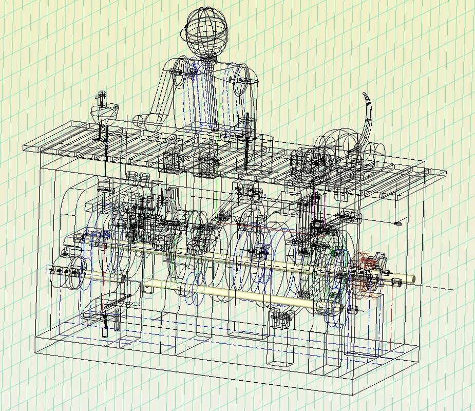
Over the last couple of days I have been wood burning fur on the dog that is to be part of the current automata. He has been posted previously in the blog. It's the kind of thing that can be a little tedious at times, as well as loud if you are using a vacuum to suck smoke fumes away as I am, since I am not working in my sj. Anyway I thought I would throw a photo of a partially burnt pooch into the blogsphere. 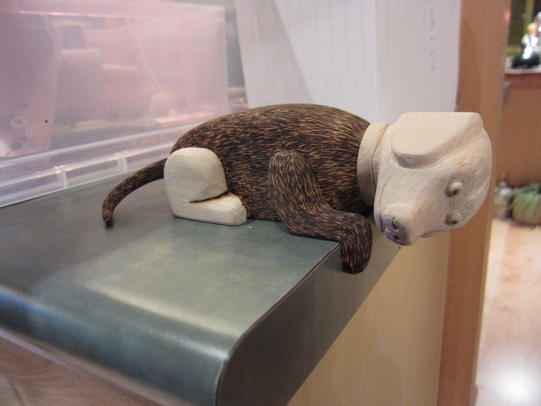
A couple of hind quarters and a head to go.
|
Why Automata?Automata is a creative blend of my life interests , engineering, art and woodworking. Archives
July 2022
Categories
All
|
 RSS Feed