So What's "The Why and How Of It" All About?

|
I am often asked questions like," How do you make this?", "How does it work?", or "Where can I get more information?", from people wanting to learn more about automata. Sometimes as I work, I think someone would be interested in this little task or trick I am doing so I should really find a way to share it. I have often fantasied about writing a book, or making instructional videos, but I'm not a good writer and I never seem to set aside time to do these. So I decided I would share little tidbits, and tricks on the website in small instalments and then maybe one day there would be enough to publish!
So in no particular order here are some of Al's "The Why and How of It" missives. |
List of Sections
1. The Ratchet Mechanism
2. The Geneva Wheel
3. Cutting Gears
4. Designing Basic Follower Arms
5. An Unusual Assembly - Plan Carefully
MORE TO COME!
2. The Geneva Wheel
3. Cutting Gears
4. Designing Basic Follower Arms
5. An Unusual Assembly - Plan Carefully
MORE TO COME!
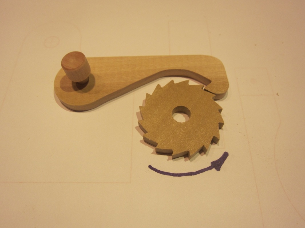
1. The Ratchet Mechanism.
.When I am building more complex automata I alway use a ratchet mechanism. There are a couple of reasons for doing this. The first is that if I want the actions of the automata to tell a story they must occur in the right sequence, running the piece in reverse may not do this. The next reason is that some of the followers that impart linear motion work dynamically better with the cams turning toward the pinned end, lifting the follower. Operating in the in reverse direction they can actually bind on some cam shapes. Limiting the direction of rotation with a ratchet prevents this.
I always strive to put the ratchet on the input shaft so as not to bind secondary components. Also the torque levels on the ratchet are the least at this location.
The photo below shows one of my usual setups. In the direction of rotation shown in the photo the toothed wheel lifts the ratchet arm allowing it to rotate freely. In the other direction the weight of the arm causes it to ride on the tooth long flat, and the pick on the end of the arm looks into the short face of the tooth preventing rotation. The angles of the arm and tooth short face should be the same to ensure locking. The pick is located so that it runs a little over the top and down the side of the wheel to enhance locking. The pin on the left lets the arm rotate freely. I also always put a small spacer, often 1/16" thick, behind the ratchet arm so it does not rub on another component. I often install this ratchet adjacent to the case wall.
There is a compromise in designing these ratchets. If you make the teeth too large then the action of the arm becomes loud during operation, even to the point of distraction. Smaller teeth run quieter but cannot take as much force. As a point of scale the hole in the ratchet wheel is 3/8" and the head of the pin is 1/2" in diameter. The ratchet arm is 1/4" thick.
This ratchet is made from poplar. Do not use basswood as it is too soft. Do not use birch plywood as the teeth can chip in operation. You may use maple or oak for added strength in some instances.
I hope this ratchets up the quality of your work!
2. The Geneva Wheel
The photo below shows a Geneva mechanism in the throws of construction. It consists of three components, the star, the backing disc with a pin in it, and a hub that attaches to the backing disk. A Geneva mechanism is used to impart intermittent motion to the output shaft through the star from a continuous rotation of the input shaft in the backing disk. The number of slots in the star define the ratio of steps in one complete rotation of the input shaft. The star shown here has four slots so it will complete one rotation when the backing disk has completed four. I believe it is geometrically impossible have a Geneva mechanism with less than three slots, but conversely there could be many.
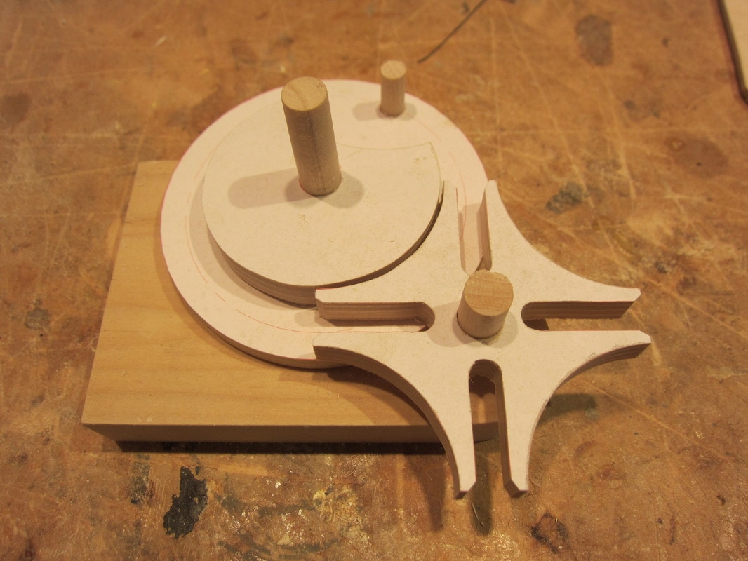
Assembled Geneva Mechanism
In an automata piece it is an efficient way to make a motion, or set of motions to occur less frequently than others. The can be independent motions or used to suspend other motions on regular cycles. Utilizing one can extend the storyline of an automata. causing viewers to observe longer to view a complete cycle of movement.
There are a few things to consider to build a smooth working Geneva mechanism. First the arcs on the star must be a close match to the outside diameter of the hub, too tight and they will interfere when rotating, too loose and the star could either under or over rotate causing misalignment for the next pin entry. The one which will occur will likely be dependent on the torsional load of the output shaft.
When cutting the hub having a poor exit profile is just as bad as the entry end of the outside diameter section. Notice also that there are small bevels on the input end of the slots on the start. A small bevel is useful to direct the pin into the slot in the case of any misalignment, but too large a bevel can cause the star to over rotate as the pin exits the slot, causing misalignment for the next pin entrance.
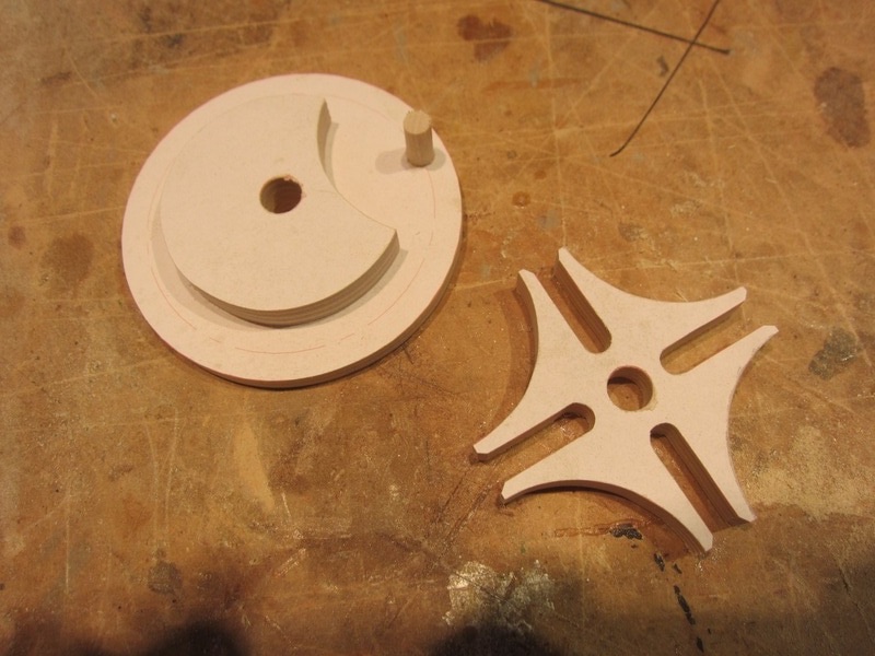
Geneva Mechanism Components
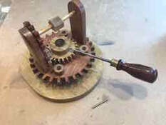
When assembling the hub and backing plate it is important that the pin be centred in the midpoint of the arc cutout. This is necessary to allow the right clearance for the star points to rotate without hitting the hub. The other important clearance is the there should be a small gap between the star and the backing disk so they do not rub on each other when turning. It should also go without saying that for smooth operation it is very important that the assembled disk and the hub be attached squarely to the shafts and the shafts be parallel. In fact good machining and align is key throughout.
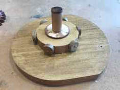
The pin need only be as long as the thickness of the star wheel, plus the length buried into the backing wheel, of course. Remember that the slots must be long enough to prevent the pins from bottoming out during rotation. Another caution is that when laying out the design check to see that the output shaft does not interfere with the backing disk. I always build a jig like the one shown to test the assembly before installing it in a piece. In fact he wheels shown here are set into the pedestal that will be used in the project!
To get a sense of size of this Geneva set, the shaft hole diameters are 3/8" and the pin is 1/4" in diameter.
As an additional guide and encouragement I have attached a short video of this Geneva set in motion.
3. Cutting Gears
One of the most common questions when viewing my work at shows from people is, "Did you cut all those gears?" Lots of Gen-xers question why I just don't make them on a 3D printer, since it seems less daunting to them. The prospect does seem challenging to a lot a folks, but It really isn't once you've done it.
The right start is key, and that is using a gear design software to create templates. There are a few different ones on the internet. I have used one called the Gear Template Generator. You can purchase a download version to run on a PC or just use the internet version. Just follow the print scaling instructions to ensure they print in the correct scale. I often design using gears that have a 12mm tooth spacing and a 28 degree pressure angle. I make them from 3/8" thick birch plywood and usually put them on a 3/8" shaft.
IMPORTANT! I add an extra 1/32" to the distance between gear centres in my design. This allows for a little leeway in the manufacturing tolerance and possible shrinking and expansion normal for wood. The gears will still perform great!
The first job is to glue the template and cut the gear from the plywood stock leaving a minimum of 1/8" from the top of the gear teeth.
See this detail in the photo on the left below. Drill the centre hole for the shaft, using an awl to locate it accurately and use a brad point bit for a clean entry. I try to stop drilling as the point emerges from the other side, flip the gear over and using the small hole as a centre, drill back toward the previous side. If the hole is not square or plumb there is not point wasting your time cutting teeth. Start over.
Here's one of Al's secret tips to maintain sanity. Whenever practical I print the cutting templates in red ink like in this photo. I do this to help distinguish the scroll saw blade from the cut line on the template on complex cuts like this. It's sounds a little wacky but I find it really helps. Try it, you'll like it!
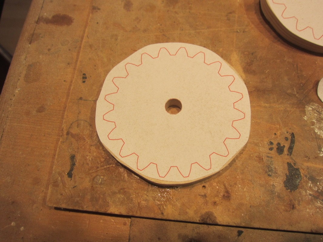
Gear template to cut out.
|
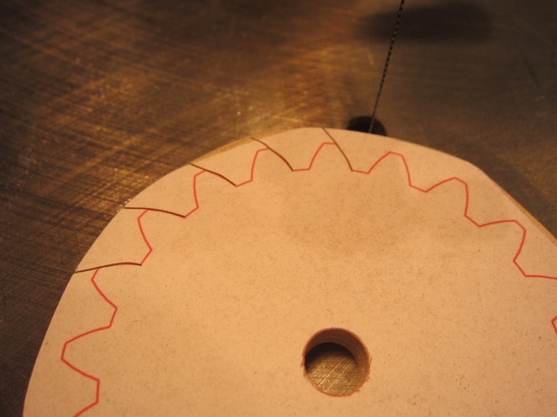
First cuts - cut only one side of all the tooth profiles.
|
Starting on either the right or left tooth faces go around the disk, cutting each tooth's profile shown in photo in the above right right. Do all the same ones to get in a smooth rhythm. The cut is a volute, a decreasing diameter curve, and cut cleanly to eliminate the line. The 1/8" edge space gives you time to line things up before you get to the tooth profile. A sharp blade is an asset. I use a new #3 scroll saw blade after cutting 3 gears. I might cut some cams in between, since a sharper blade is not as critical for that operation.
Next cut down the opposite profile, turn and cut across the bottom of the tooth profile intersecting the previous cuts. Make sure you cut off or below the red line on the tooth valley bottom to avoid contact with the meshing tooth. When it's all done your gear should look like the one on the left below.
Next cut down the opposite profile, turn and cut across the bottom of the tooth profile intersecting the previous cuts. Make sure you cut off or below the red line on the tooth valley bottom to avoid contact with the meshing tooth. When it's all done your gear should look like the one on the left below.
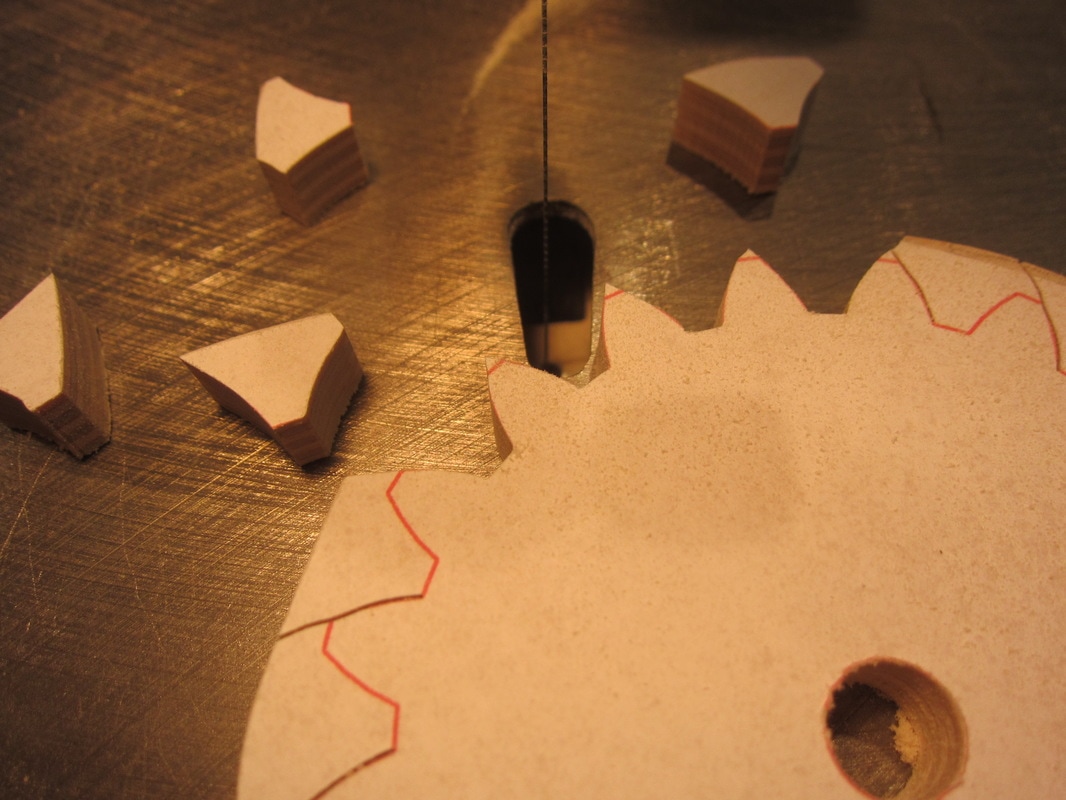
Cut the opposite tooth profile and bottom.
|

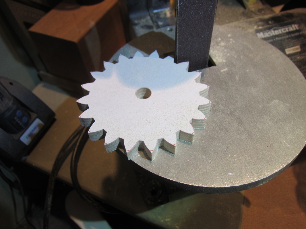
Cutting complete - hope it resembles yours!
|
If you have wobbled when cutting your teeth, you can clean off the tooth surface to the red line with a file, sandpaper, or by using a small bench sander like the one in the photo below. (120 grit) Lastly sand off the tooth of the teeth, again eliminating the red line. Make sure each tooth is square to the sanding surface as you do this. It is much easier to do this than it is to try and cut the small amount of remaining material.
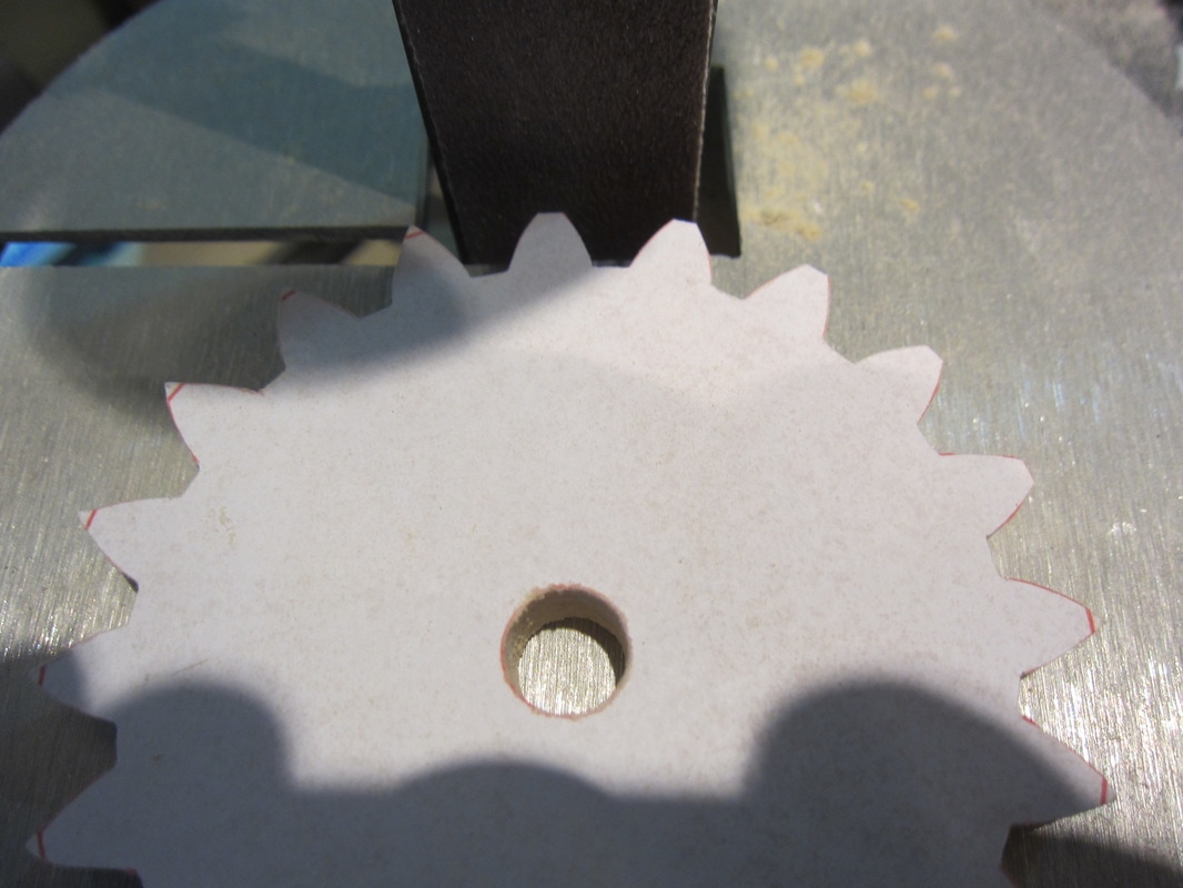
So now you have a nice looking gear, but does it work well?
So now you have a nice looking gear, but does it work well?
|
|
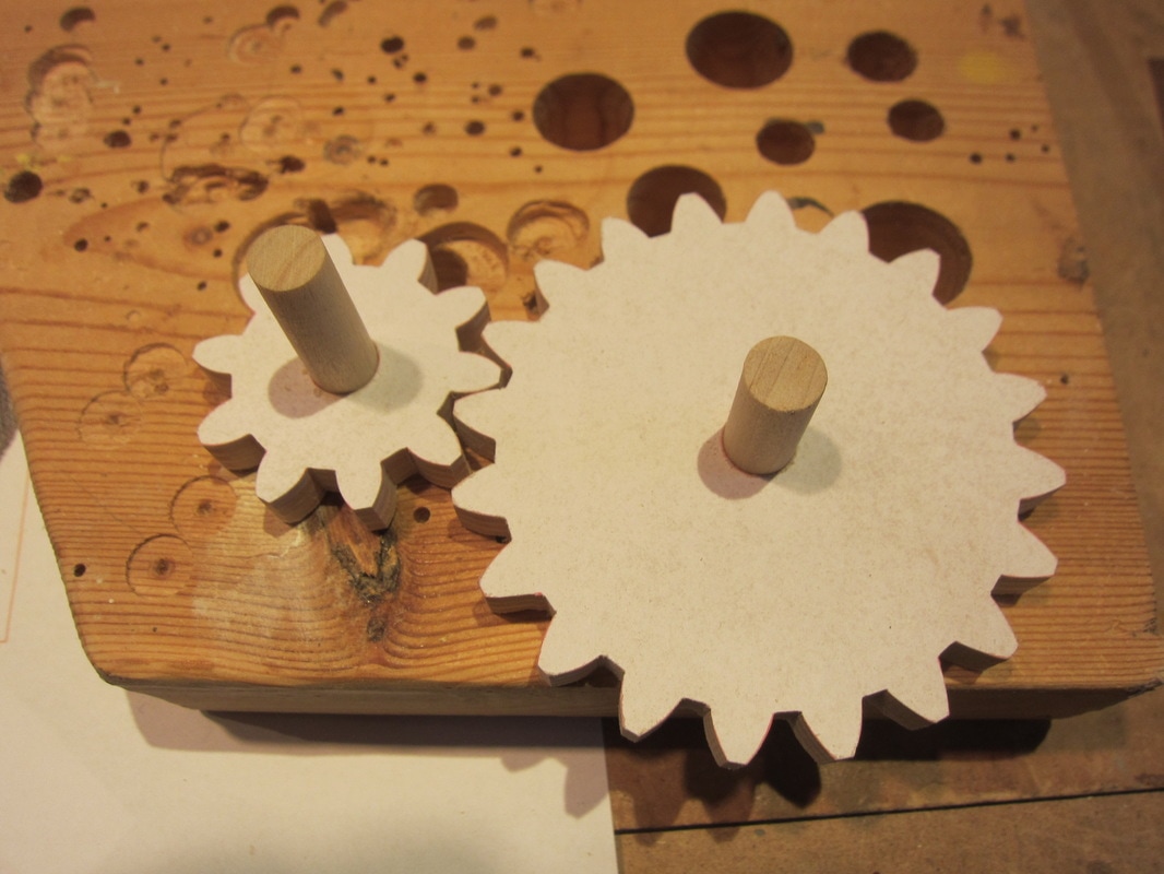
To check your work, drill two holes pin a piece of wood to match the separation distance between the two gears in your design. Stick a short piece of dowel through each gear and give them a spin. (See photo below). They should move freely. Notice the slight separation between the gears in the photo. Machined metal gears would virtually touch here. As they spin observe the gap between the two gears. If the centre hole is off centre you will see the gap open and close as they spin. If any teeth "bottom out" either sand more of the tooth top or deepen a tooth valley as appropriate. If a tooth pinches sand the tooth profiles a bit more. Now just remove the template paper and your done! That wasn't so bad was it?
To see how rugged these gears can be watch the testing of the gear box video on the Mechanisms, Tips & Tricks webpage.
To see how rugged these gears can be watch the testing of the gear box video on the Mechanisms, Tips & Tricks webpage.
4. Designing Basic Follower Arms
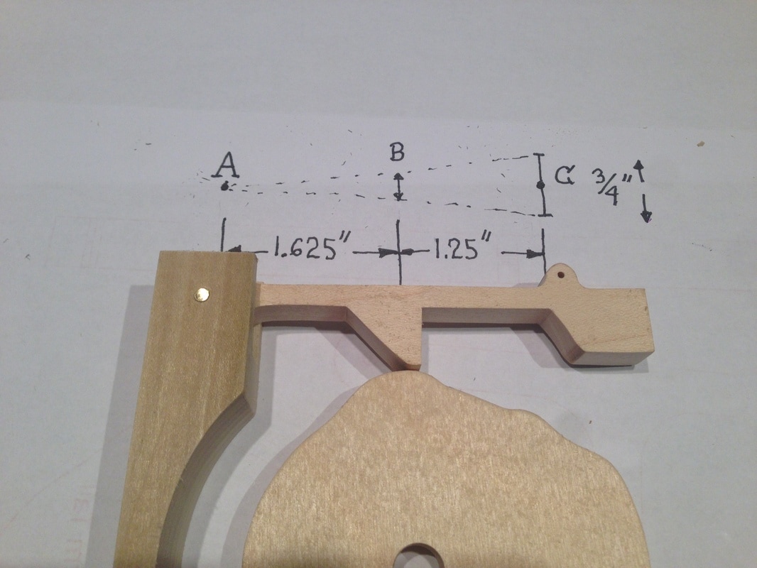
So for those that are a little geometrically challenged here's a primer on designing a simple follower. This one is going to have a wire connected at point "C" which is going to go up through the top of the mechanism case and move something up and down. In this example it is required to move up and down 3/4" (0.75"). The objective then is to figure out how much the point on follower that rides on the cam will go up and down. This will tell us how much to change the diameter of the cam to get the required action a point "C".
Okay time for some math. Point "A" is anchored. Some call it the fulcrum or anchor point. In this case however, it can, and will, rotate around the 1/8" brass pin in the pedestal. We can ignore all the angle calculations. All we need is the ratio of the length of the lever arms "AB" and "AC" to do the calculation.
So "B" will move ((1.625/(1.625 + 1.25)) X .75". That equates to 0.424". So to get the action you need, if the cam you design has a 2" minimum diameter, then the outside diameter must be 2" +(2 X 0.424") = 2.848" diameter. Now you just need to decide when it will be up and when it will be down, and how fast it will transition from one to another.
5. An Unusual Assembly - Plan Carefully!
|
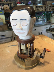
Every time I create an automata I find one of the things that must be thought out carefully is how it will be put it together in the final assembly. Usually I try to design a wire link into mechanisms that can allow for a precise final adjustments. Things don't always work out this way. Here is an example of a more complex sequence of steps to do a final assembly. The project is a meditating gentlemen who despite his calm expression is fighting his inner demons. There is a lower structure that imparts a spinning action and contains the main mechanism components and an upper part that contains the character action bits. Here is a look at the finished project. |
|
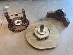
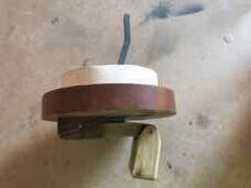
The two sections are assembled separately and then fitted together as the last step, otherwise the head and cage cannot be installed. Lets start with the base. Here are the main fabricated parts of the base, the baseplate, the handle pedestal, the roller plate, and the spinning mechanism assembly. A few other bits will be identified as we move along.
The first step is to install the 3/4" dowel post in the base insuring it is perpendicular to the base and fitting it to the correct length after trial assembly.
The first step is to install the 3/4" dowel post in the base insuring it is perpendicular to the base and fitting it to the correct length after trial assembly.
Next slide the roller ring down over the dowel post and glue it onto the baseplate. This ring has rollers around the outer edge to help support the weight of everything above and allows it all to turn easily. There is a washer plate in the centre the same thickness as the protruding wheel height for additional stability. It is lubricated with wax on both sides to reduce friction. It is not glued in place and can spin or not as it chooses.
Next, lower the assembled mechanism assembly onto the dowel, drop the inner gear into place and install the pin that keeps the gear from rotating. I used an awl to help locate the predrilled hole. All the alignment for this operation was predetermined by fitting the pieces together previously to ensure proper fit and clearance. At this point the assembly will spin freely while the gear and base remain stationary.
|
|
Now the pedestal with the right angle pinion gear can be installed. If installed first the main turntable will not go into place. This pedestal assembly is slid sideways into place and secured with screws from below. I do not glue this component into place in case disassembly may be required for a future repair. The photo shows a temporary handle in place, but normally the permanent one would be installed at this time.
Next I install the four dowels in place that hold up the upper mechanism, only gluing the bottom ends at this time, but using the upper assembly to align it while the glue dries.
The follower from the upper assembly must fit properly with the cam on the top of the lower assembly seen in the photo above. The final joining of the two assemblies will determine how well the piece operates; too loose not action, too tight it binds!
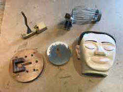
Here are the components of the upper assembly, a top plate, a head base block, the follower, the Inner Demon, the cage, and the face block. The connection must be made between the Inner Demon and the follower, before the head is installed.
If you look at the large base plate on the front left of the photo there are holes that allow access to screws that hold the face onto the head base block from the bottom, the last step in the upper assembly.
If you look at the large base plate on the front left of the photo there are holes that allow access to screws that hold the face onto the head base block from the bottom, the last step in the upper assembly.
First attach the top plate and head base plate together and then install the follower into the support bracket on the bottom of the top plate. This is the follower that requires critical alignment when fitting the two assemblies together.
The next step is to install the "Inner Demon" by pinning and gluing him down onto the head base block and connecting the attachment plate on his back to the end of the follower with a pin. You can check the motion by moving the follower up and down from below.
The next step is to install the "Inner Demon" by pinning and gluing him down onto the head base block and connecting the attachment plate on his back to the end of the follower with a pin. You can check the motion by moving the follower up and down from below.
|
The Inner Demon Has to be able to fit into the cage through the bottom ring of the cage. In this case it was necessary to raise his arms above his head to drop the cage down over him to secure it to the head base plate. At his point you should also secure his hands to the cage. This part is very finicky as incorrect hand placement can cause things to bind up.
Hopefully it should look something like this video clip to the right. |
|
Finally screw and glue the face into place from below and the upper assembly is finished! Now for the critical last step. apply so glue to the top of the dowels and slide the two assemblies together. Make sure the follower and cam are correctly aligned, faces parallel and just touching. Turn the mechanism to ensure smooth operation. If if catches or binds, raise the upper mechanism slightly. Work quickly before the glue sets!
Hope you enjoyed this little assembly overview. The process often requires some thought before starting out. If you haven't already seen the finished project go to the Inner Demon webpage.
Hope you enjoyed this little assembly overview. The process often requires some thought before starting out. If you haven't already seen the finished project go to the Inner Demon webpage.