|
Off the design table for a while and a busy couple days cutting out pieces for my next piece in the shop . (Subject is still a deep dark secret!) As an engineer you just have to love gears. So here I am cutting a larger gear on the scroll saw. For the larger sizes I like to use the spoke design, not to reduce weight, but just to add to the sense of motion when the piece is operating. For me the automata show is as much below the the table as it is above. 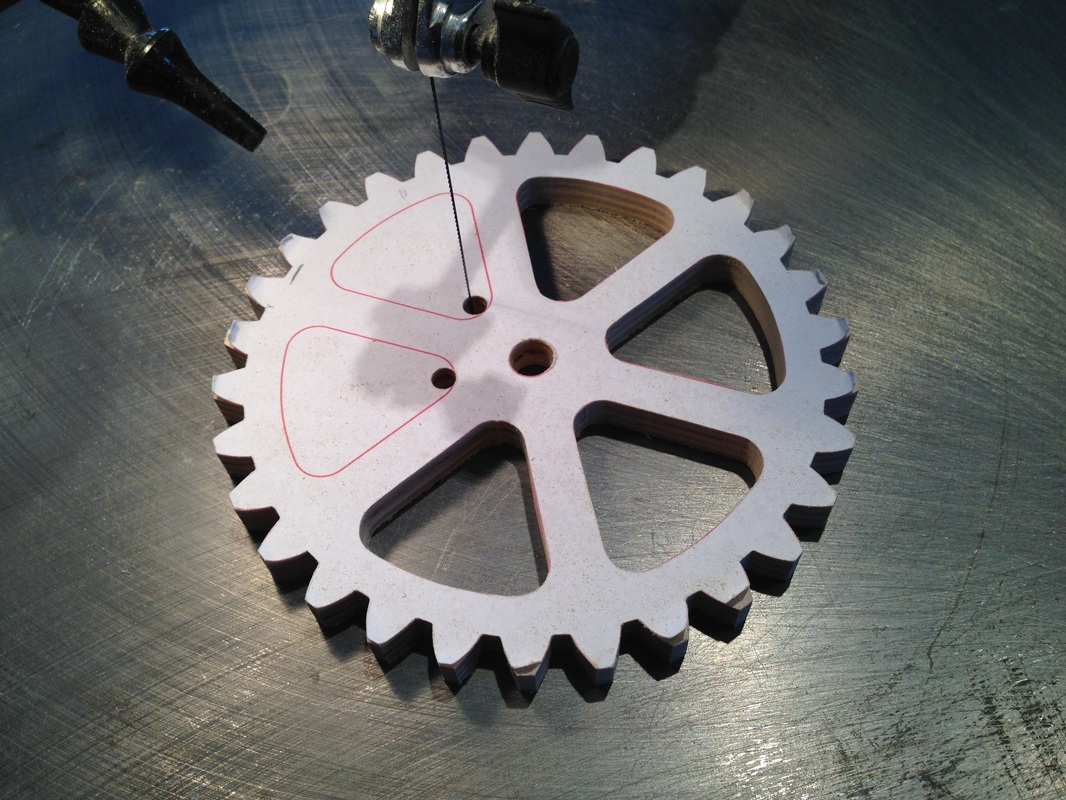
Here's the finished gear pair temporarily placed in their pedestal to check for clearances. 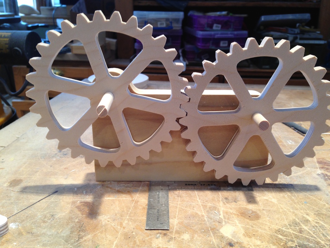
0 Comments
Right now it's a lot about production. Having most of the CAD design done the next usual step is to lock yourself in the shop and bang a a bunch of pieces from the design. This early view of the Box 'O' Bits is mostly pedestals, shaft supports, some spacers, and a wheel. A lot more to do! 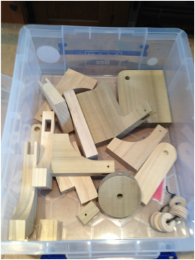
It's always a treat when things work right the first time. Here's the two big gears from a few blogs back being run in the pedestal. This is the time to check the teeth for meshing. Being just a little bit off centre on the shaft holes can wreck havoc on the operation. There is only so much you can do with the gears at this point, so if you need to increase the distance between shafts, now is the time to find out before you build the large components. The sound in the background is the music in my shop! Oops! Ok, last chicken picture for a while. I finished the third bird between the shivering spells. Minus 30 degrees C this weekend! Anyway I threw a Canadian penny in for scale e this time. Two of the girls seem interested in it. Say high to Chickeletta, Chickita, and Chickeisha. 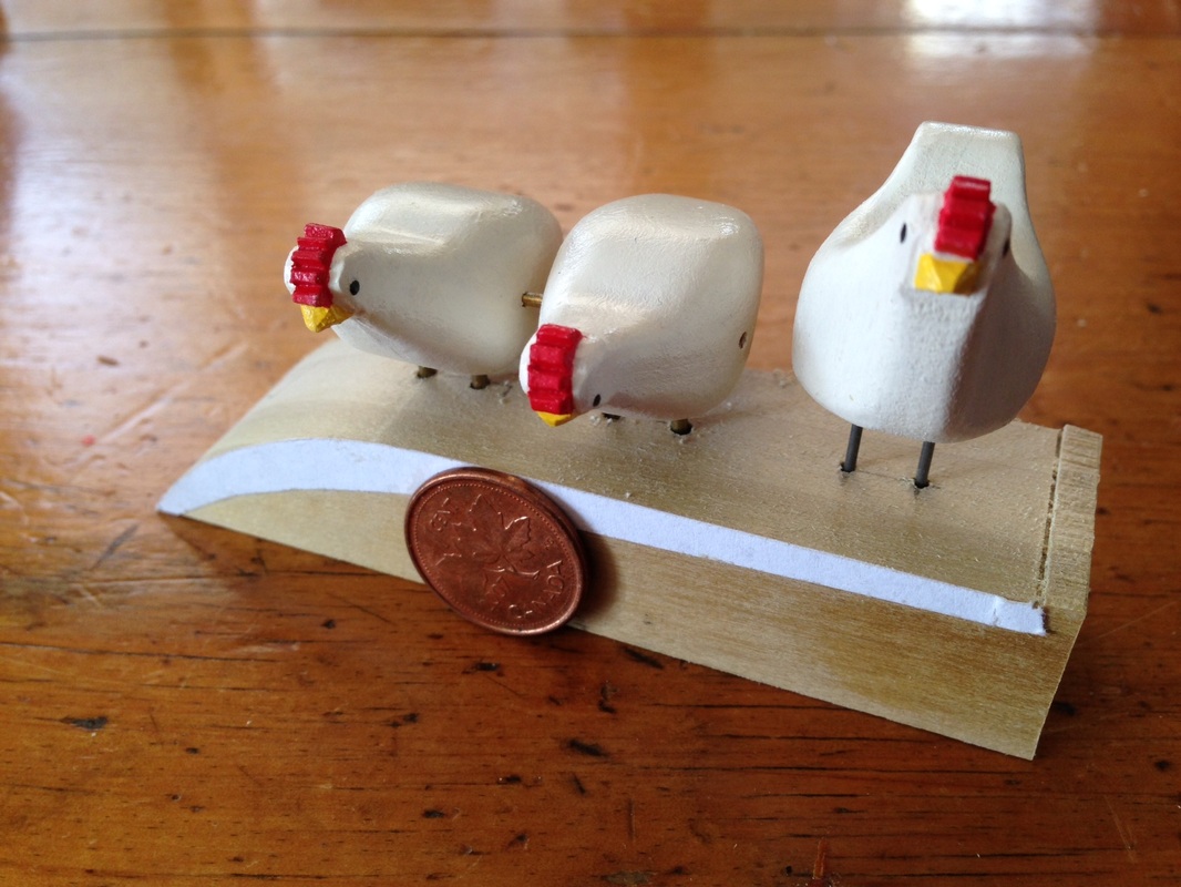
Snuck in just a little time and managed to paint two hens and carved the last one. 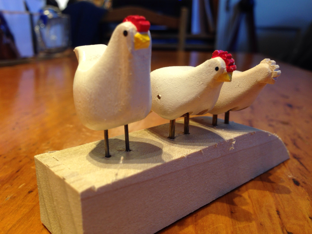
Will I did manage to get a little time in the shop this afternoon and I spent the time seeing if I could build some little chickens as an accent on my next piece. It's an experiment to see if I can make them small enough to suit the scale and still be able to make them move. 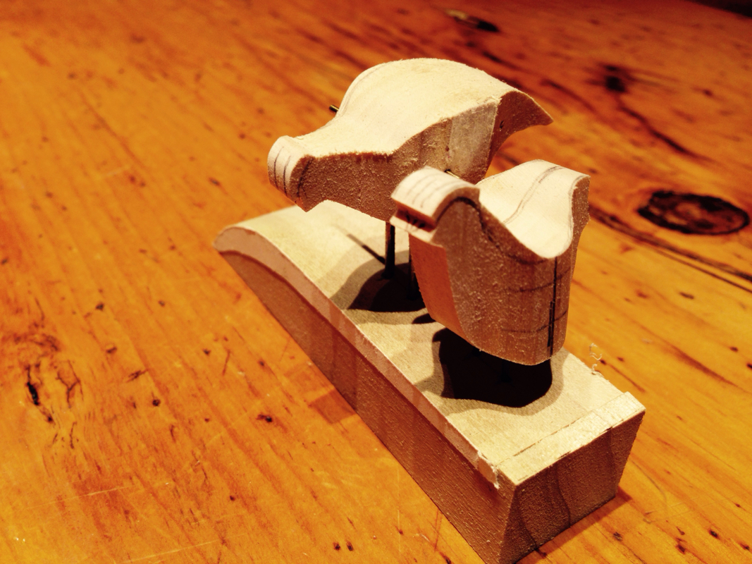
This photo shows two chickens roughed out. One will move in pecking motion and the other stand still. 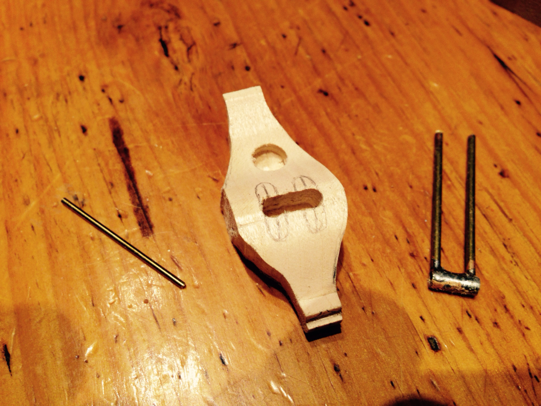
This is the underside of the pecking bird. The soldered assembly is the pivot tube mounted on the top of the legs. A pin through the body will go through the tube as the pivoting axle. The hole (1/4") in the rear will receive the actuating link. No photo today, just a note to say I'm still alive since I haven't posted for a while. I'm currently working madly on the design of my next piece on my CAD software so I haven't been out cutting things in my shop for a while. Still a few mechanism hurdles to overcome.
I always find myself going a little overboard on the CAD detail, especially the characters, knowing full well that when I start carving they will become whatever they will become! Family Day in Canada this weekend so we'll be hanging out with the grandkids. I just it was going to be warmer out. Minus 30 degrees C with the wind chill! Ouch! I've had a request to make another piece where someone lounges in a comfy summer chair. Whether you know them as Muskoka or Adirondak chairs they seem iconic summer symbols. Here's the current edition. It's two inches wide. 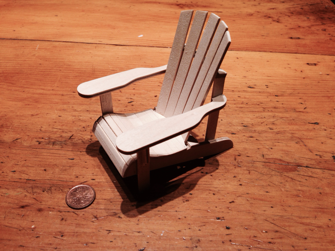
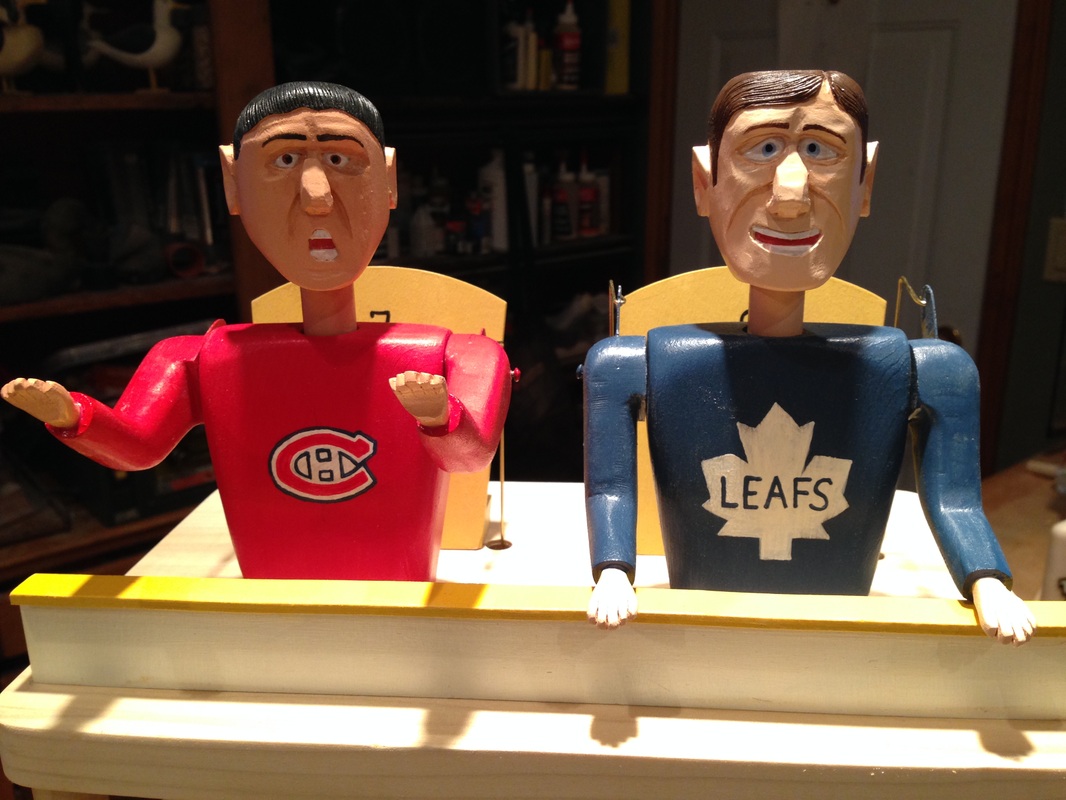
I had someone ask about my small "Leafs Score" automata. After some back and forth we agreed that I would make the same concept using on the "Raving Fans" design. The mechanism runs smoother and the slightly larger size would allow me to use carved heads. So here is the result! 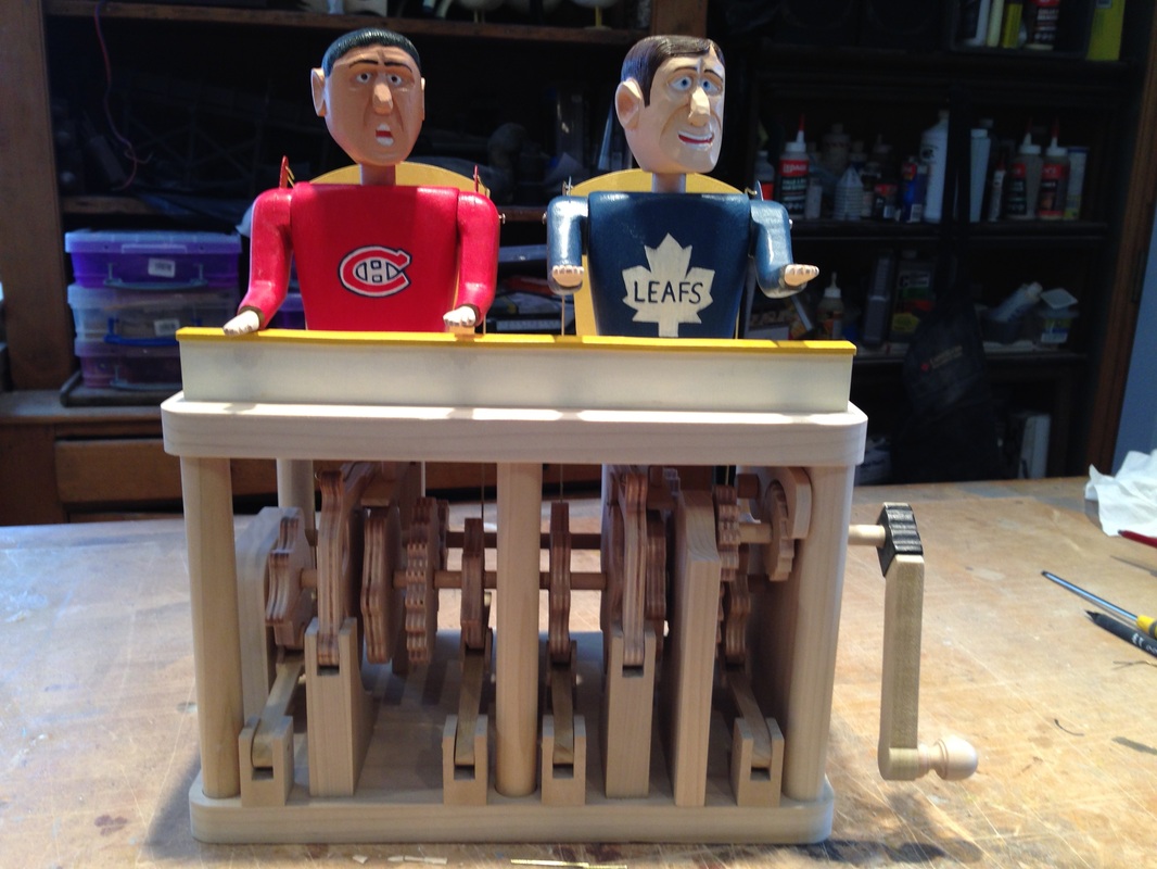
When making automata there is sometimes need for careful thinking. For me, gluing together a large camshaft always requires focus, and I often wait until I'm mentally set before starting. The combination of getting things in the right place, in the right orientation, and at right angles to the shaft while working with CA adhesive is sometimes adventurous. Even though I thought I had preplanned carefully when doing this camshaft, I found on assembly that I had reversed the position of two cams on each side and that the head movements expected were not as planned. Here's a photo. 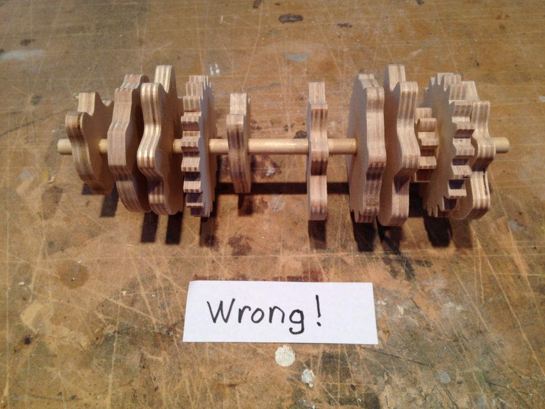
The second and third cams from the left are reversed as well as the sixth and seventh. This is where a good $#@&* is usually warranted. Here is the new one. 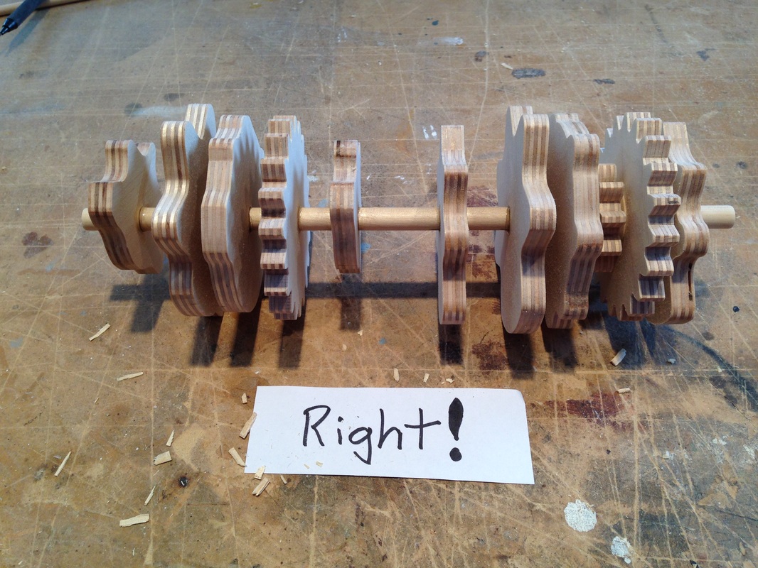
So how did I do it? One choice is to chuck it in the garbage and start anew. Another is to try and recover the gears, since they require more work to make, and scrap the cams. Lastly you can try to save all the pieces, sacrificing only the shaft. I chose the last one. Here's how it goes. Cut the shaft, in this case 3/8" diameter, out from between the cams/gears leaving a little protruding out on each side (1/16"). Drill thru the dowel using a drill 1/16" smaller diameter that the shaft size. (Make sure when drilling you have the cam flat. I placed it over a 1/2" hole that received the short stub on the other side.) Here's what a cam should like after doing this. 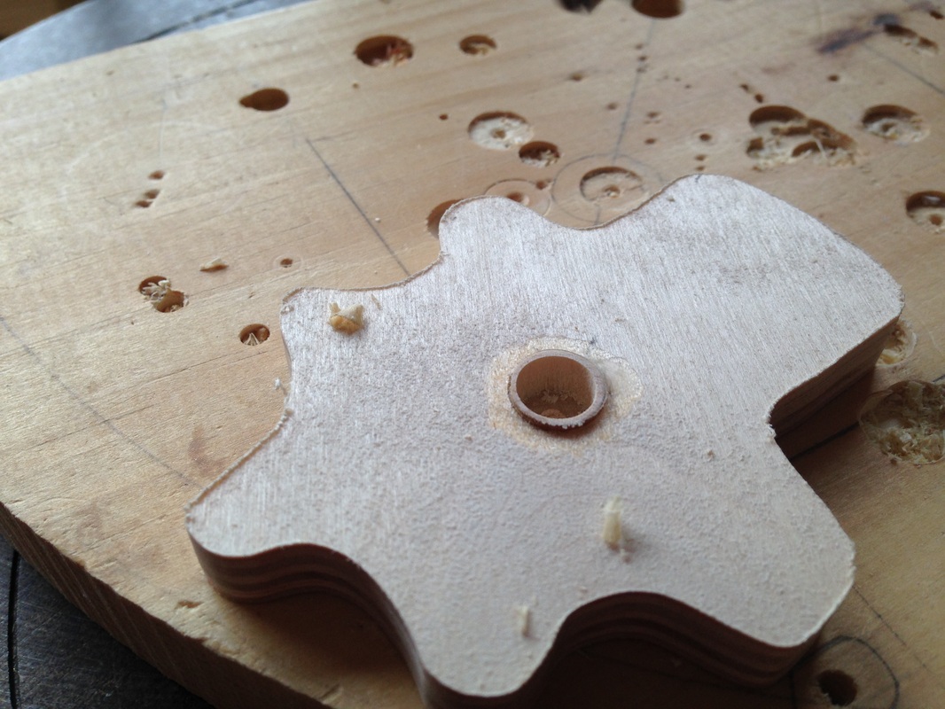
Now using a utility knife, moving around the circle, carefully push the tip down into the remaining dowel splitting it slightly several times. Repeat on the other side 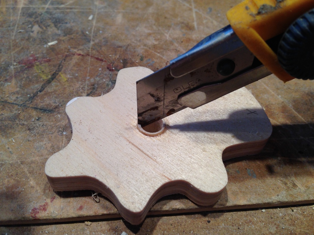
Next using a flat object, like the blade of a small slotted screwdriver, push the dowel remains inward until they break. Do both sides. You really only need to get one side completely clear so you can re-drill the original original hole. I do both sides and remove as much dowel material as I can just to ensure better drilling accuracy. Sand the backside of the cam/gear flat so it lies flat for drilling. Using a forsner bit carefully drill out any remaining dowel bits and glue. Now you can assemble the cams/gears on a new shaft. 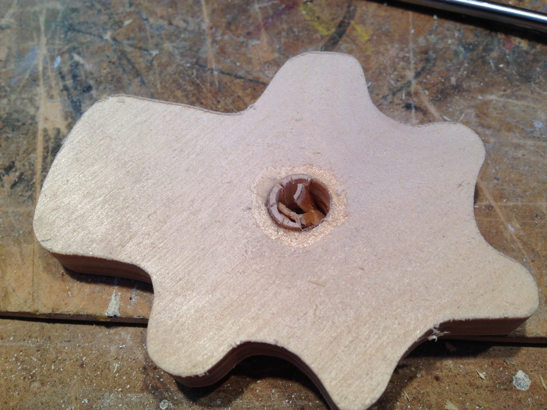
|
Why Automata?Automata is a creative blend of my life interests , engineering, art and woodworking. Archives
July 2022
Categories
All
|
 RSS Feed