|
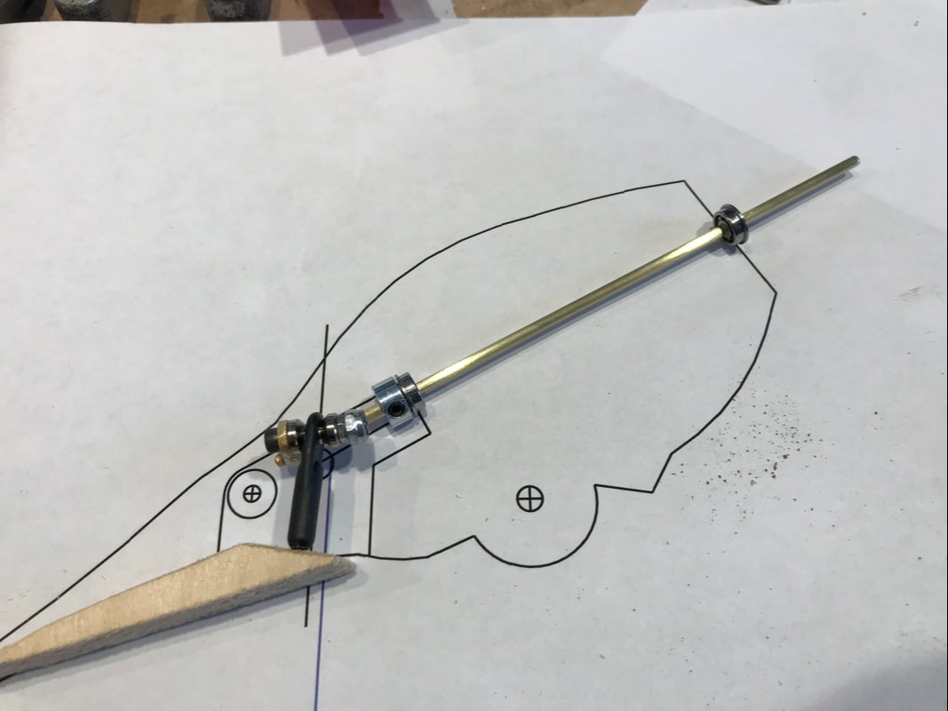
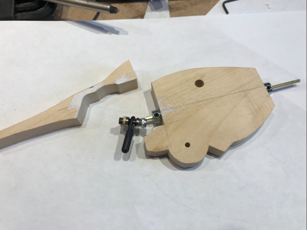
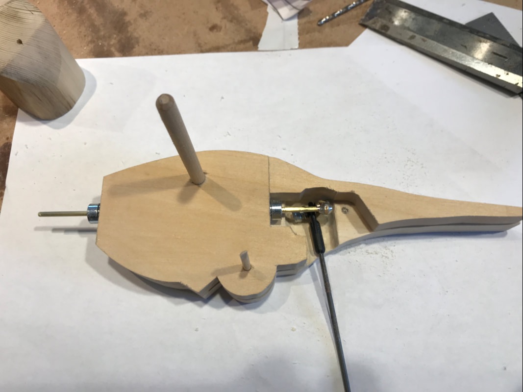
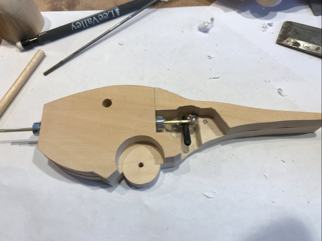
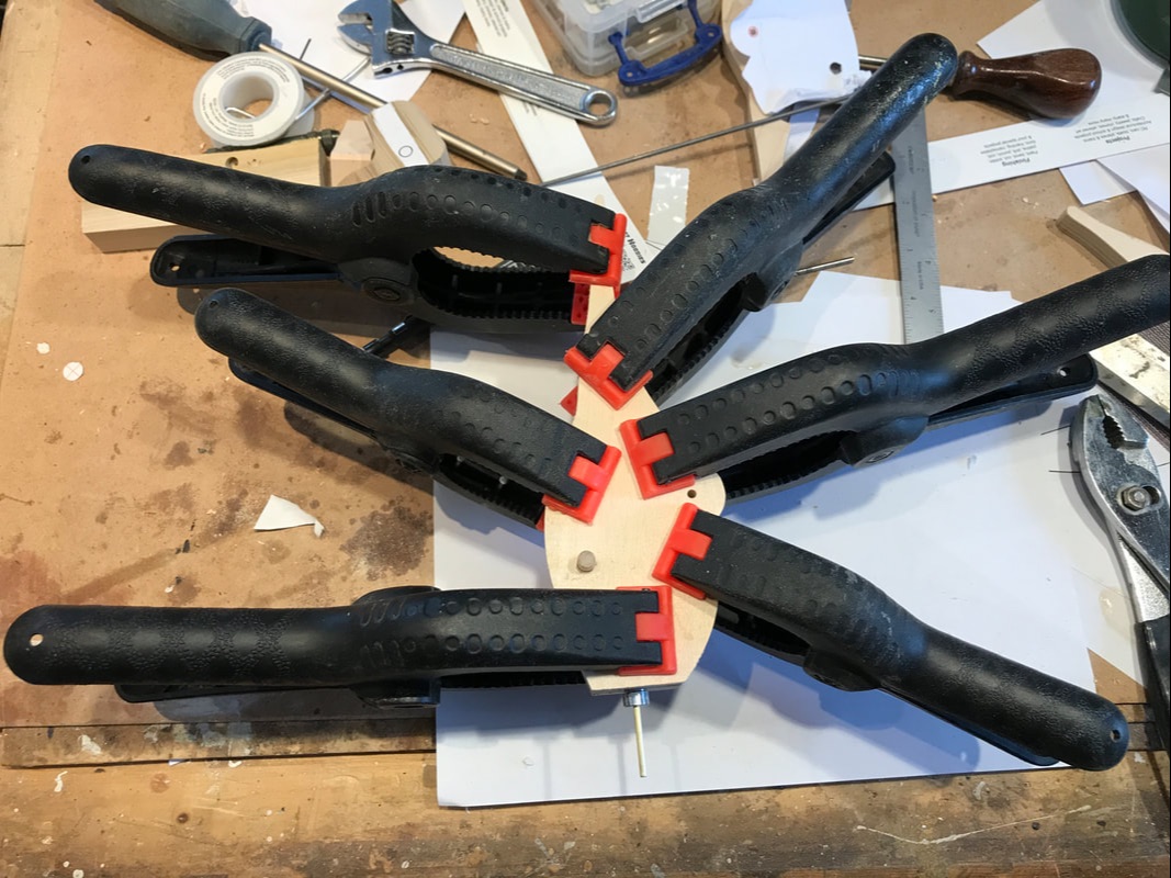
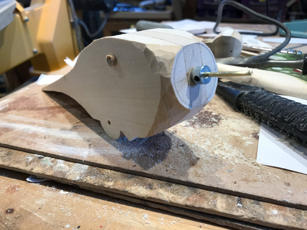
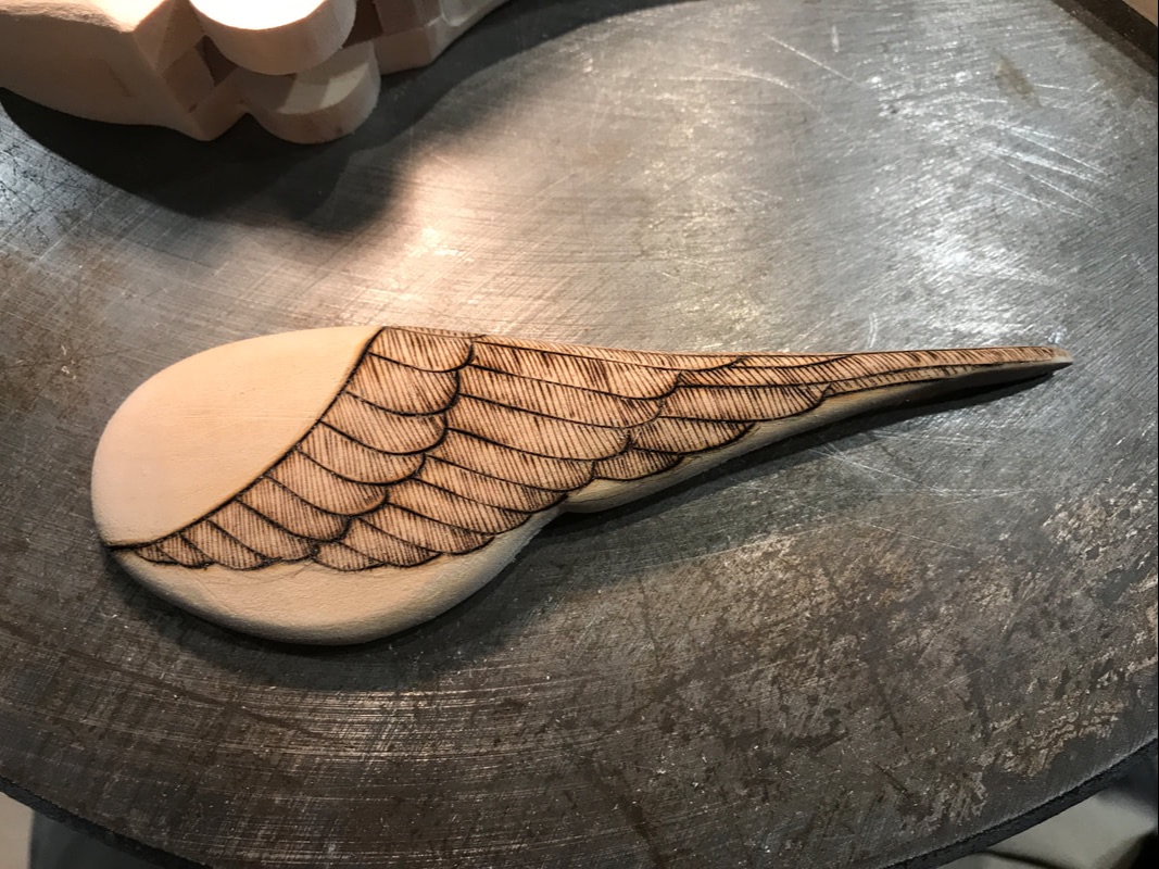
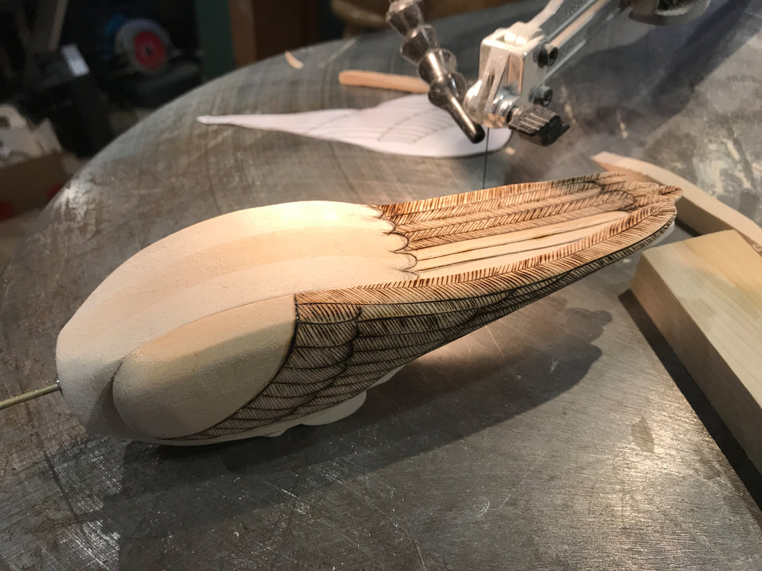
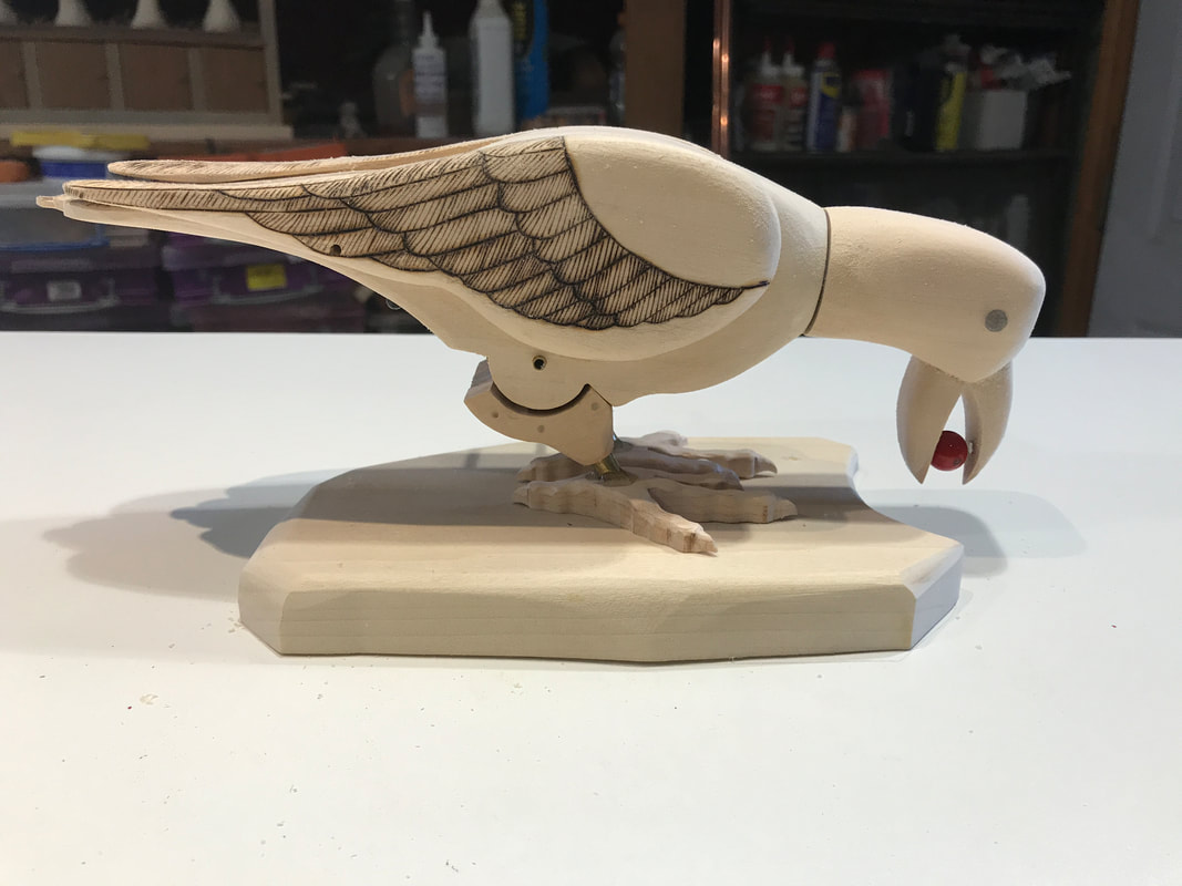
Every now and then you come across a project that begs to have part of the mechanism hidden inside the automata character. This usually means you have to build the moving parts inside as you fabricate the rest. You have to take care because once sealed in, it's a major mess to tear things apart again. This is one such example. The photo on the left below shows a drawing of the torso of a bird without it's head and legs drawn. the head will be on the upper right on the brass rod. This bird will tip forward and then return to a standing position. As it stands it's head will turn to look at the viewer. The tipping linkage connection and pivot point can be installed from the outside of the bird, but the mechanism to turn the head must be built inside the body of the bird. Since this is an exhibition piece there is the added complexity of bearings and collars required to ensure long term operation. There is a 3/32" brass rod that extends through a 1/4" hole in the block. At the top end there will be a small bearing and a shaft collar. Only the flanged bearing is shown here. The collar will serve two purposes. It will keep the shaft from sliding down into the body and will be firmly attached to the head to prevent loosening of the head. The lower end also has a bearing and collar to hold the shaft in the correct position. Finally a brass plate is soldered onto the shaft at an offset that allows it to turn. It is bent slightly to help prevent binding as the bird rocks up and down. On the end of this small plate is a universal joint, the type used in RC cars and airplanes, that will connect with a rod to the mechanism in the base. The connection is through a threaded rod inserted into the black sleeve. On the right is the mechanism as it sits in the body block. what is important to note is that to insert this piece, a segment of the body had to be cut out to allow it to slide in from the left side of this photo. Once installed the little wooden piece was glued back onto the block. The body of the bird is shaped from three body blocks of which this is the centre one. The photo on the left below shows the reverse view of the centre block sitting onto of one of the outer body blocks. Note here that some of the thickness of the outer block has been removed to give the lever arm enough space to rotate, enabling the head to rotated through about 90 degrees. This is sort of a chew-it-away with a Dremel burr until things move smoothly job . The little black pencil dot is the location of the linkage hookup for the tipping motion. The hole will be drilled when the body is assembled. The picture on the right has the spot for the pivot disc on the leg assembly cut out. It was the subject of a previous blog entry. The 1/4" diameter hole is drilled through all the body blocks to help maintain critical alignment as I build. Next, place the other side block on, check all the alignments, sand everything smooth so there is nothing to catch one and glue it all together. Be smart with the glue though, you don't want to glue your internal bits together! When it dries, start shaping the block into the semblance of the bird. At this point it looks more like a Sopwith Camel! Next, make a pair of wings and add a little pyrography to get the appearance of feathers and also burn in a few tail feathers. I never profess to build perfect carvings, but rather give the semblance of the character that allows me to build things inside and provide movement. Finally, although not finished in this next photo below, add a head, and a beak with a few magical bits in it and you begin the see "Rocky" the caching raven emerging hiding a precious berry.
More to come!
1 Comment
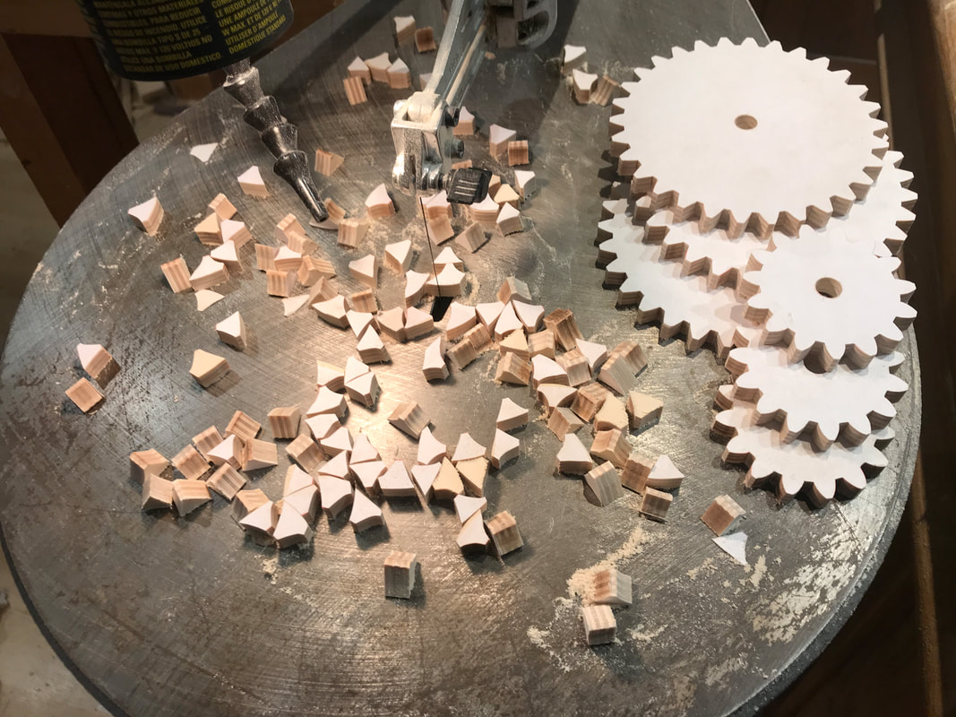
Spent some time cutting wooden gears for my current project. What you see are the cut gears and the mess that cutting 135 teeth can make in your shop. I actually find it sort of relaxing, it gives me a chance to tune out for a bit, put some music on, and just cut away. You still do have to pay attention of course. I still do get asked a lot about making wooden gears, like "Why don't you laser cut them? " or "Why not 3D print them in plastic?", or "Why not use metal ones?"
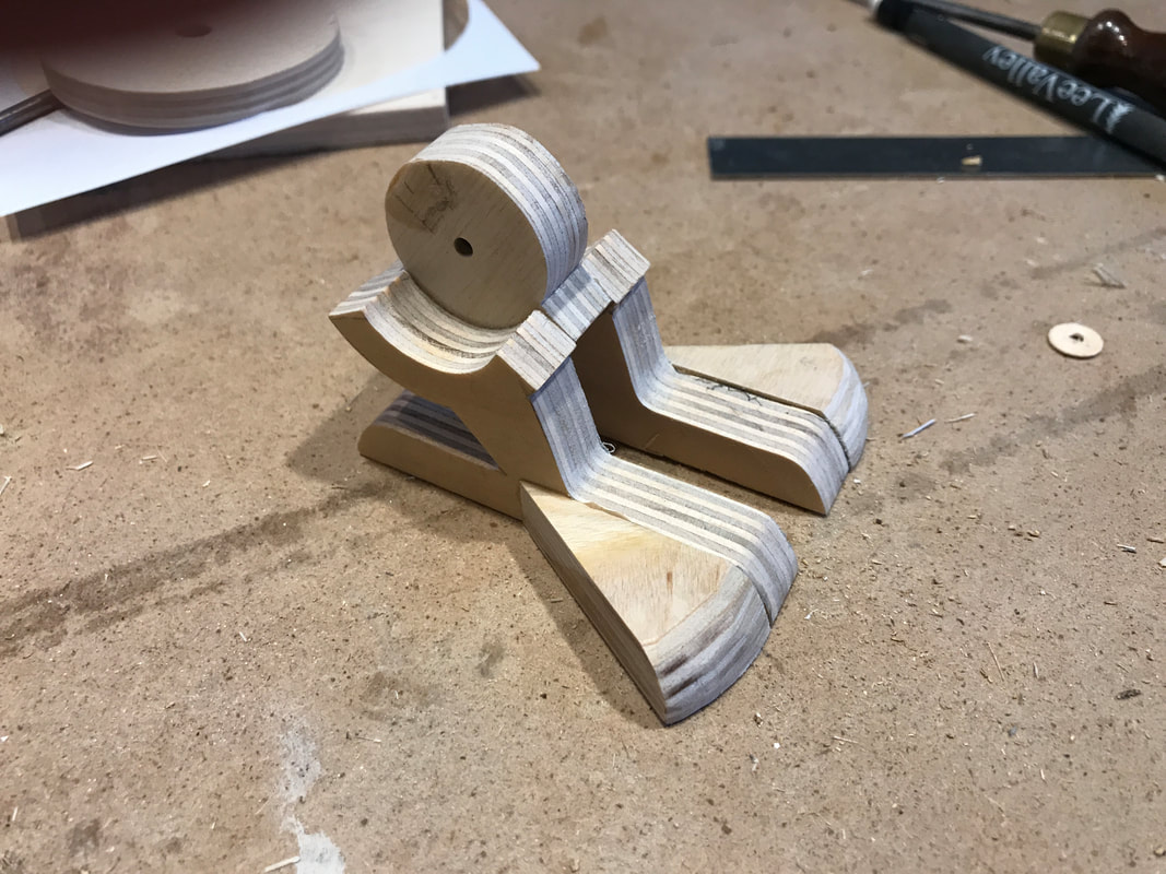
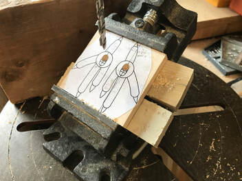
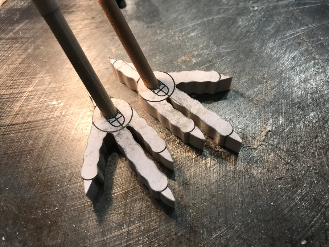
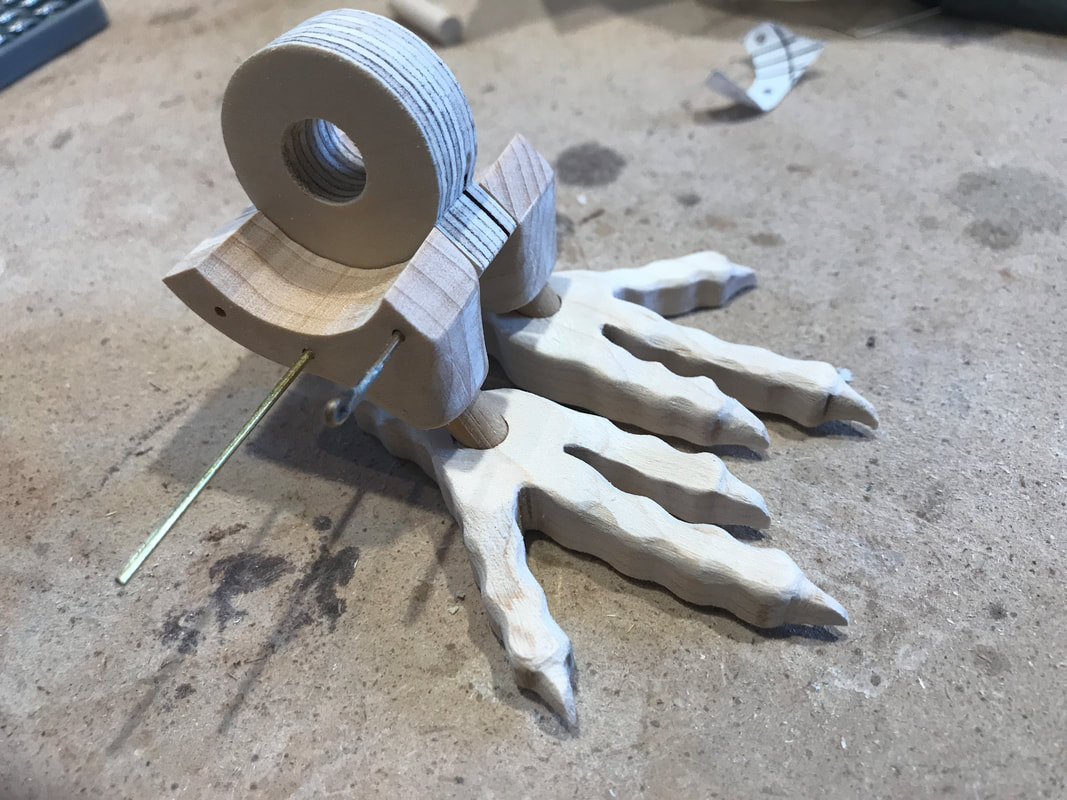
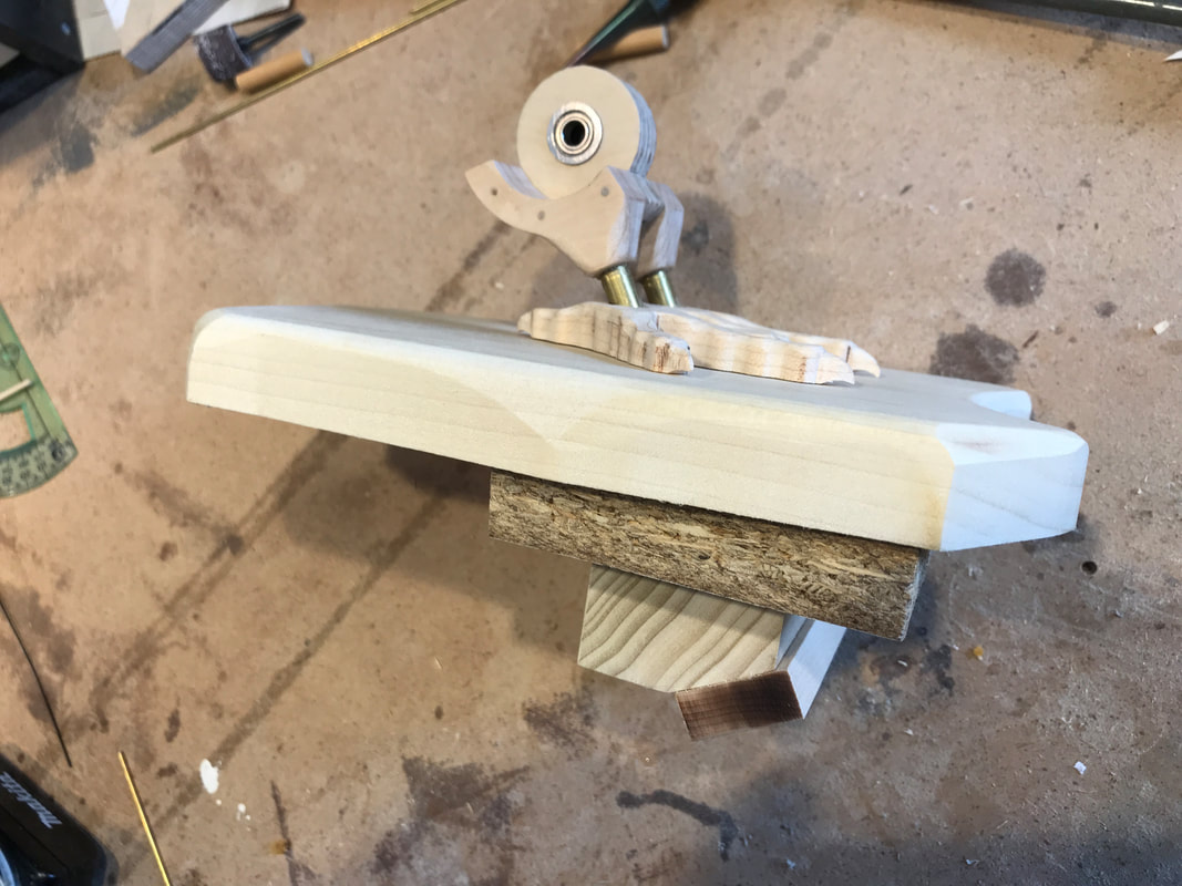
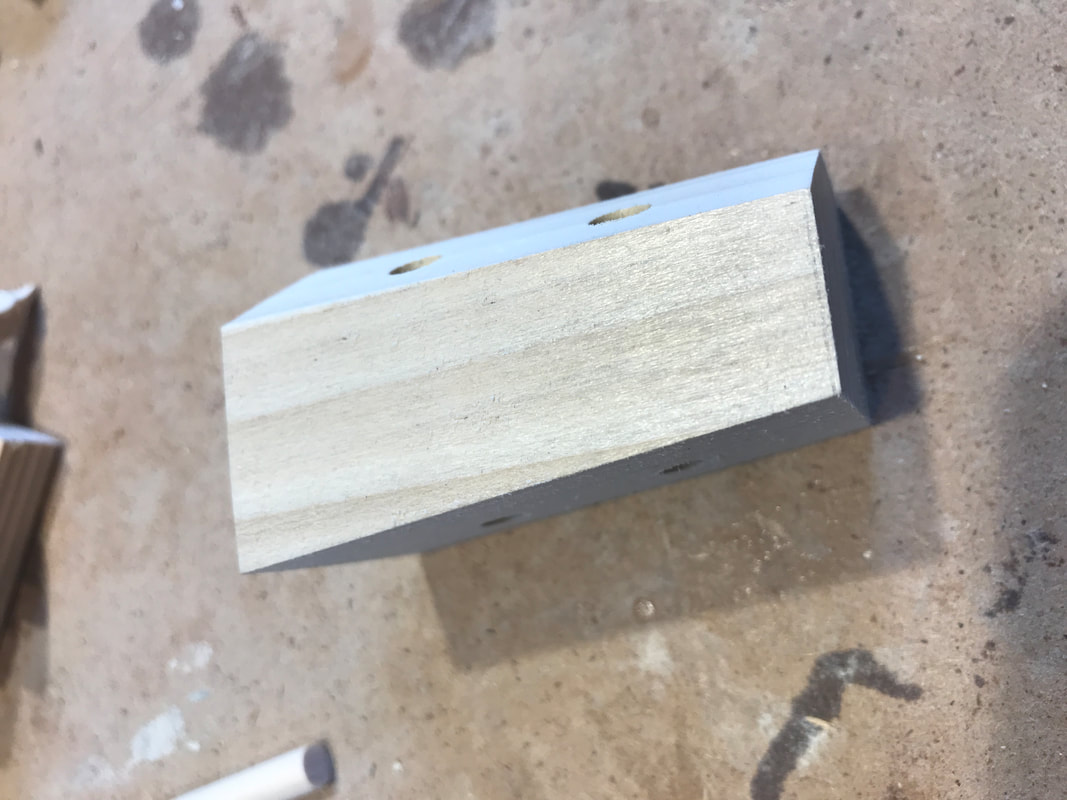
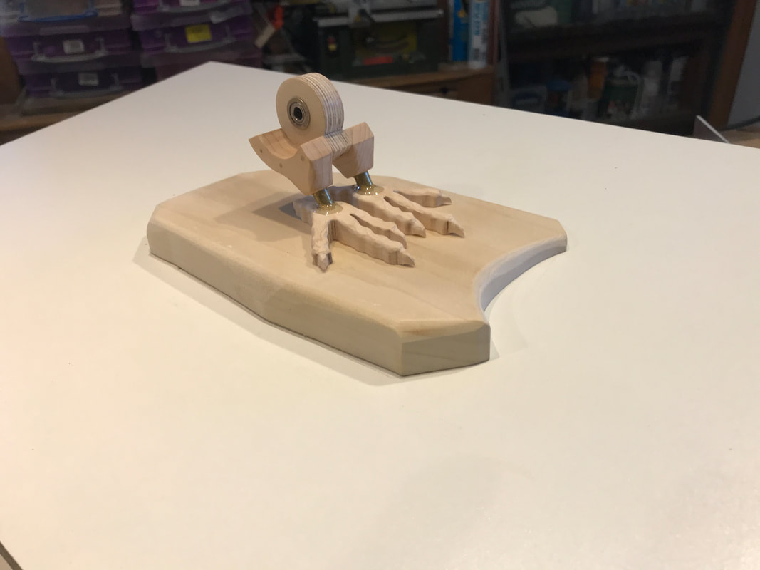
Well silly or not here is why. One of the best ah-ha moments when people see my work is when they notice the gears are made from wood. It surprises them I guess. Folks likely think of metal or plastic as more expected materials for gears. Next they usually ask where I get them. When I tell them I make them myself on a scroll saw they are taken aback. They think I'm crazy! They expect there must be an easier way and usually that starts a long discussion about other ways of making gears. In the end there is a bit of awe when they think about it. And that is the moment I enjoy when someone sees part of my work as awesome. It has sparked a fleeting moment of joy, or delight, and we are just talking gears here. There are many things awesome about making an automata and collectively they make it fascinating to many. I am not a production shop. I tend not to hurry but make things that I see as unique. To me building automata in wood adds to the novelty, quirkiness and uniqueness. So every time I sit to cut wooden gears I don't mind spending a little time to create a little awesome! Now if you excuse me I need to get the vacuum out. Putting tools to wood the last few days on the second automata piece I am making for a museum exhibition. I've been busily designing an educational piece for a display which is a Raven "caching" food to prepare for a cold winter. The automata will be operated by the visitors to the museum by a wheel on the front of the display. As such, I have tried to make it as rugged as possible, yet still characterizing it as a handcrafted construction. There are protective clutches, stops and metal components all designed to withstand the riggers of a public display. Typically automata that go to collectors experience limited operation over their lives, but one in a museum will see many hours of operation, operated by viewers of all ages. This means more mechanical bearings and metal parts than I generally use. I am having a lot of fun making these adjustments. The leg assembly, subject of the blog, shows the extent of the scope change and careful planning! I introduce to you Rocky, (at least part of him), a raven who is caching a small berry he has found in preparation for the winter. He is hiding it in a small crevice in some rocks in a wintery scene. He repeatedly retrieves and replaces the berry while looking around to see if any other ravens have noticed him. The first thing to examine are his feet and legs and their construction. The photo below is the prototype I made to help figure things out. The disk with the hole is the centre of the rotation for Rocky pivoting up and down. Where I had designed these before with brass tubes and rods, this piece will require a metal bearing. The feet look like ducks feet, but don't worry - remember it's a prototype! The greatest concern is that it supports the weight of all the raven and needs to be strong. While square plywood legs might provide great strength they will not cut it for authenticity! This component also needs to be well anchored to the baseplate, preventing movement, however being able to remove the raven for any reason would be advantageous. Okay, lets get started with the feet. They are an interesting feature to observe and should bear a good resemblance to a real raven's feet. I will use 1/4" brass rods for the legs extending into the base, so this means the feet can be more delicate and life-like, since the will not carry any real load. . On the left you can see the feet I designed sitting in my drill press vice. I am drilling 1/4" holes for the legs to extend down through the feet into the base. This is about a 30 degree angle as a raven's legs incline forward from its body. On the right you can see the feet cut out and wooden dowels stuck into the feet to illustrate the fit. I make pieces that resemble reality, not replicate with 100% accuracy. This approach is needed often just to make the mechanics work. An overzealous birder might notice in the photo that the raven's toes have three bumps on them where in reality they have four. Four looked to dainty to me considering the rest of the raven so i went with three. My apologies to serious bird people 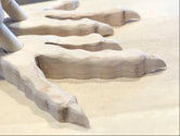 With a little Dremel tool work, some sanding and a little sweat, the feet get a fairly realistic look that passes my filter and I move on to making the pivot cradle that is the upper leg joint. It is made of three separate pieces, two outer pieces of maple for strength and shape-ability, and the disc shaped centre piece of birch plywood that will ultimately hold the metal bearings. Before cutting and shaping the maple blocks the time is right to drill the 1/4" holes for the brass legs while the blank is square. Shown below is a test fit up off the leg assembly. You can see some temporary brass rods holding the pieces together for the photo. The centre disk will be glued to the two outer maple upper leg blocks. I decided some additional reinforcement would be a good idea. A tight pin will be installed in each of holes as I glue the pieces up. The pins will be recessed a bit and hidden with wooden plugs and sanded smooth. You can also see the disk drilled out to receive two shoulder bearings, one inserted from each side. Examine the photo on the left below and you will find a few new elements. The bearings have been assembled in the disk. Small wooden plugs have been installed to conceal the reinforcement pins. Brass bars have been installed, replacing the temporary wooden dowels. A few new items have been added below the feet. The top one, adjacent to the feet, is a poplar block that is a flat stone that the raven stands on. It is tapered to match the slope of the display bottom. The next piece is 5/8" particle board, the material that the bottom of the display is made from. It acts a temporary spacer for fit testing here. Next is an odd shaped poplar block that is also shown alone in the photo on the right. It has two holes drilled through it to receive the lower part of the brass legs. Finally, looking back at the photo on the left, there is a small leg block attached to the very bottom that supports the weight of the legs, (Hard to see in the photo. It is the piece with sanding burn marking on its end). In final assembly the leg block becomes rigidly attached to the underside of the display bottom to support the weight of the raven. The upper flat stone block will be fastened to the top of the bottom plate. The complexity of this arrangement is that the display platform slopes 9 degrees down to the front of the display while the legs slope 30 degrees from vertical toward the right. Drilling these compound angles into each of these components can be tricky. The end result is shown below. The legs of the raven sitting are sitting on a level stone on the inclined floor of the display. A little epoxy has been added to help shape the transition between the feet and legs. The whole leg assembly can be lifted out of the base to remove the raven if necessary. Small holes for the linkages to actuate the bird are yet to be drilled.
Its a complicated description but I hope I have explained things that help you understand my thoughts as i design and build it! |
Why Automata?Automata is a creative blend of my life interests , engineering, art and woodworking. Archives
July 2022
Categories
All
|
 RSS Feed