|
Heres a quick video taken from my cellphone in the shop. Sorry for the audio background, I forgot to turn my sound system off. It is Loreena McKennitt singing a fairly melancholy song, probably appropriate for poor captive Chester.
0 Comments
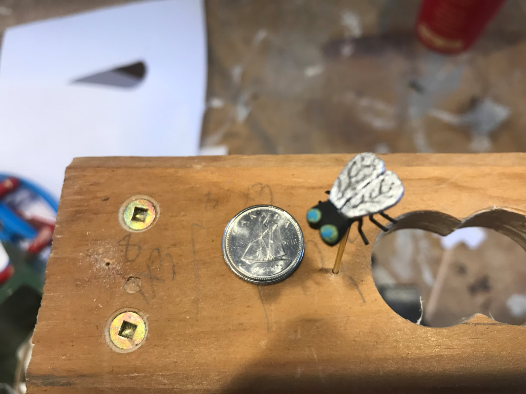
If you are a young boy and you catch a frog and put him in a bottle he'd probably catch a fly for him to eat. So I added a fly into the bottle. He is in the left front corner. As you can see from this assembly photo, he is about the size of a dime. Here's the fly in the bottle! A little change in the project has brought on a name change. The frog has some stones around him in the bottle now. They were put in by the little frog’s captor to be a token gesture to create a pleasant environment while enduring this frustrating captivity.
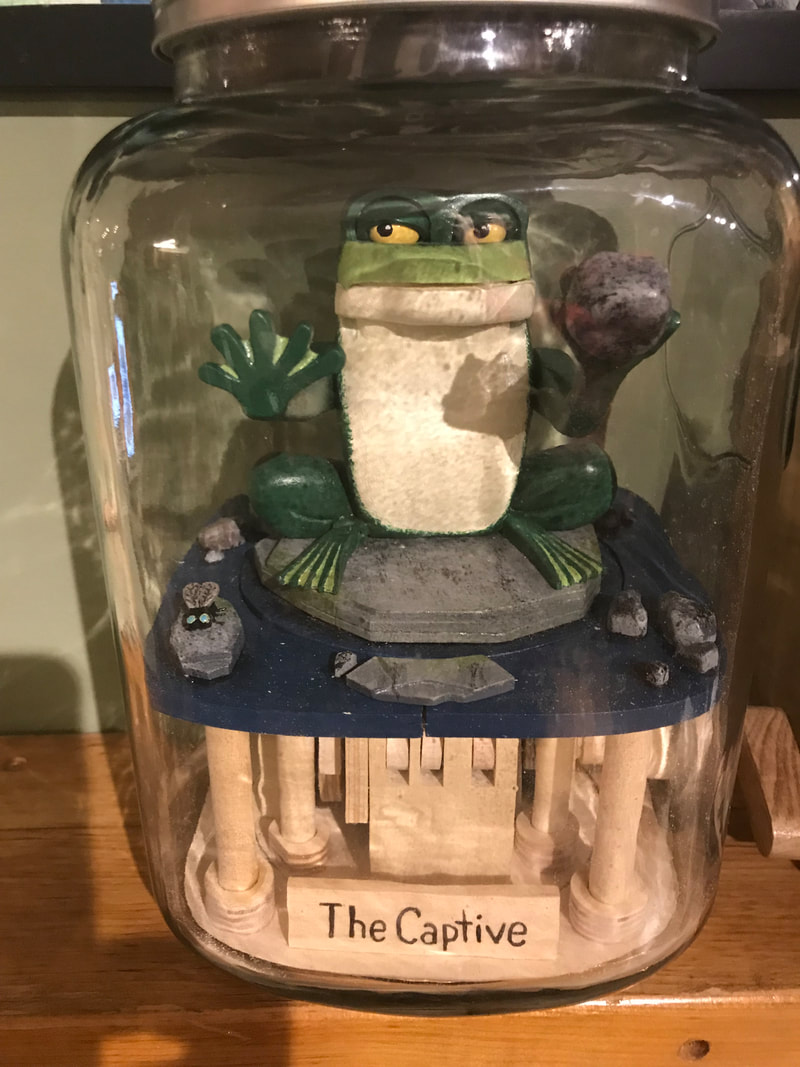
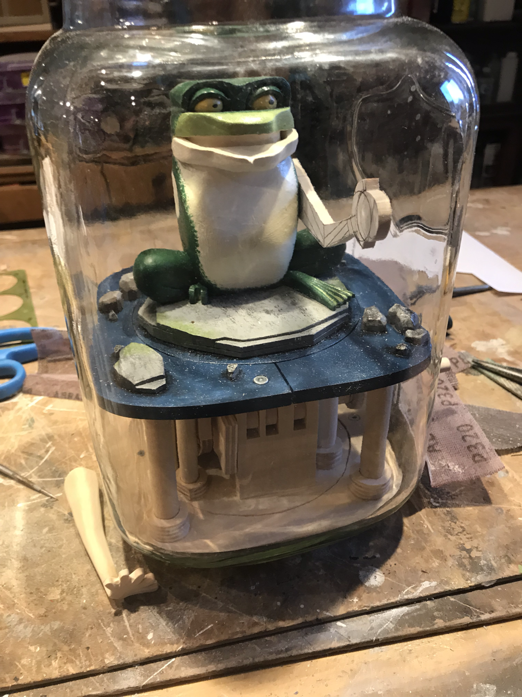
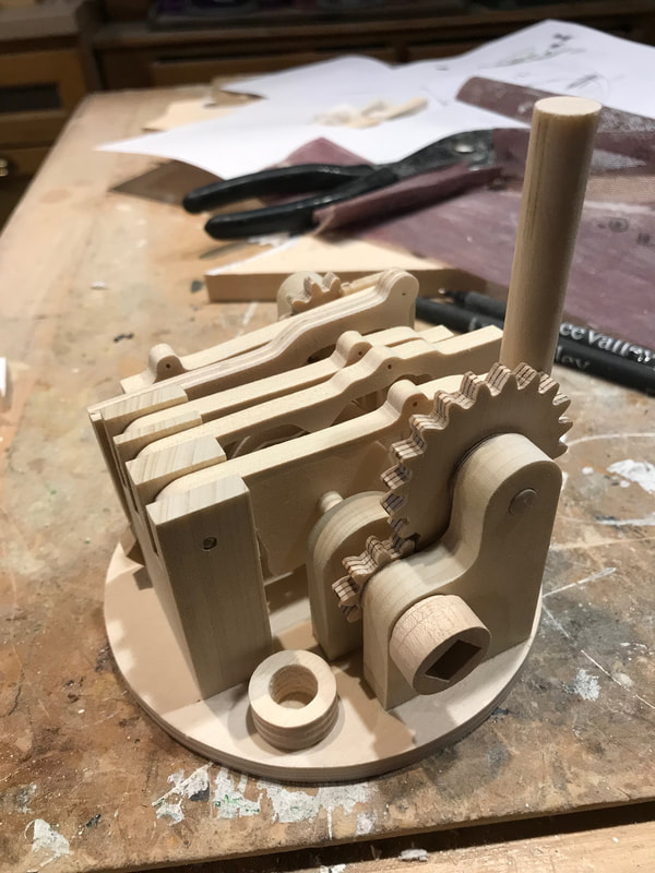
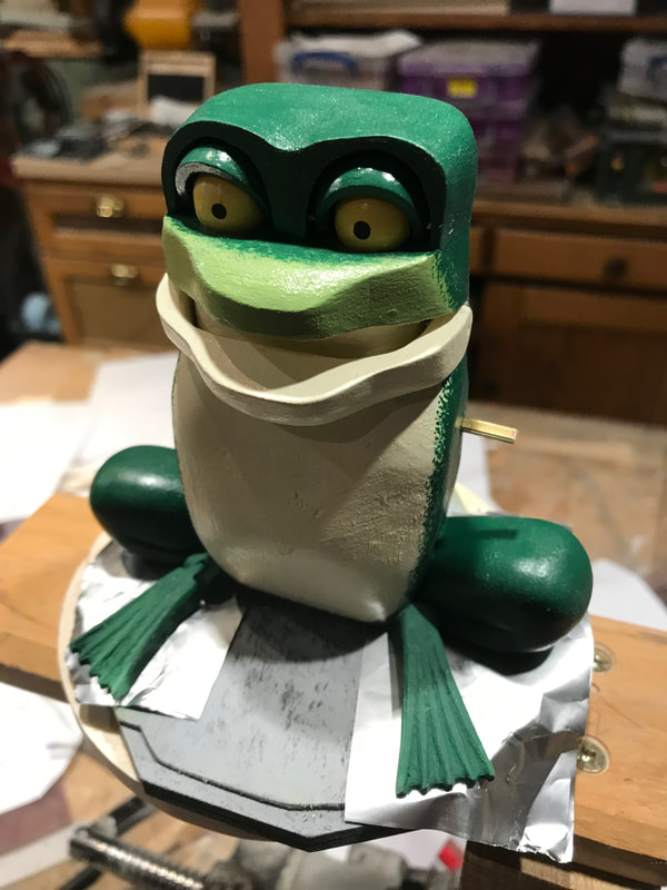
This frog is clever. He has grabbed a stone and taps it on the inside of the glass to attract the attention of someone passing by who might free him. So a little pebble in his hand has moved him from a lab specimen in a jar to a child’s captive curiosity. Therefore I have relabelled the project “The Captive”. Here is the latest photo. He sits in the bottle while I fit his arms. His right hand is made and lies on the workbench beside the bottle. It will be installed so his palm pushes on the glass. A prototype for his left arm sits in place to determine length and angle for the permenant arm. It will move to tap the pebble on the glass. Once the arms are prepared the frog will be removed and the mechanism will be tested and secured and the final assembly will begin. Well, I'm still plugging away on the internals of my frog in a bottle. As I said before I'm going back and forth between the character and the mechanism. You can see below that the mechanism is coming along. There is even a couple of cams in the middle of that clump placed on the main shaft. A dowel is sitting in the place for a future pillar that holds the top just to give you an idea of things. The bushing in the foreground is for another pillar. The followers front to back in the photo are for; the frogs right arm, the eyelids, the mouth, the eyeballs and the left foot. I need to work on the frog to locate the actuation point for the frogs foot and the amount of movement needed to make the cam. So below you can see some recent work on the frog. So here's what is happening with the frog. He has a new rock to sit on the provide some interest in the piece and you can see he is getting two lower limbs. The left one will move up and down. They are being glued in place, so the foil in the photo is to prevent the feet from being glued to the base. That will come later after the mechanism for the foot is designed and the channels are cut in the rock.
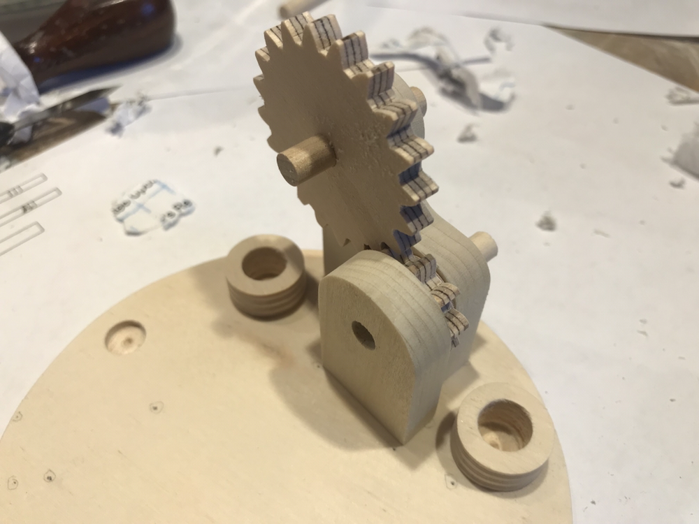
More to come! I’ve started assembling the plug-in that will drop into the jar with the frog on it. It also contains all the mechanism. These are the smallest gears I have ever cut from birch plywood. The smaller gear is 10 tooth, 3/16” wide and just under 1” in diameter.
The base is 4-1/2” in diameter. The small collars on the base are for pillars that with support the top plate where the frog will sit. The shaft for the large gear will extend to the left side. The little shaft was a temporary fit-up piece. Uncharacteristicly I am jumping around a little on this one ( no pun intended) switching between the mechanism and completing the frog. I guess we will see what happens in the shop today. A view blogs back I showed you a glass jar that will contain the latest automata project. It is actually a punch dispenser. I have a plan to have the hand crank protrude from where the spigot normally fits through.
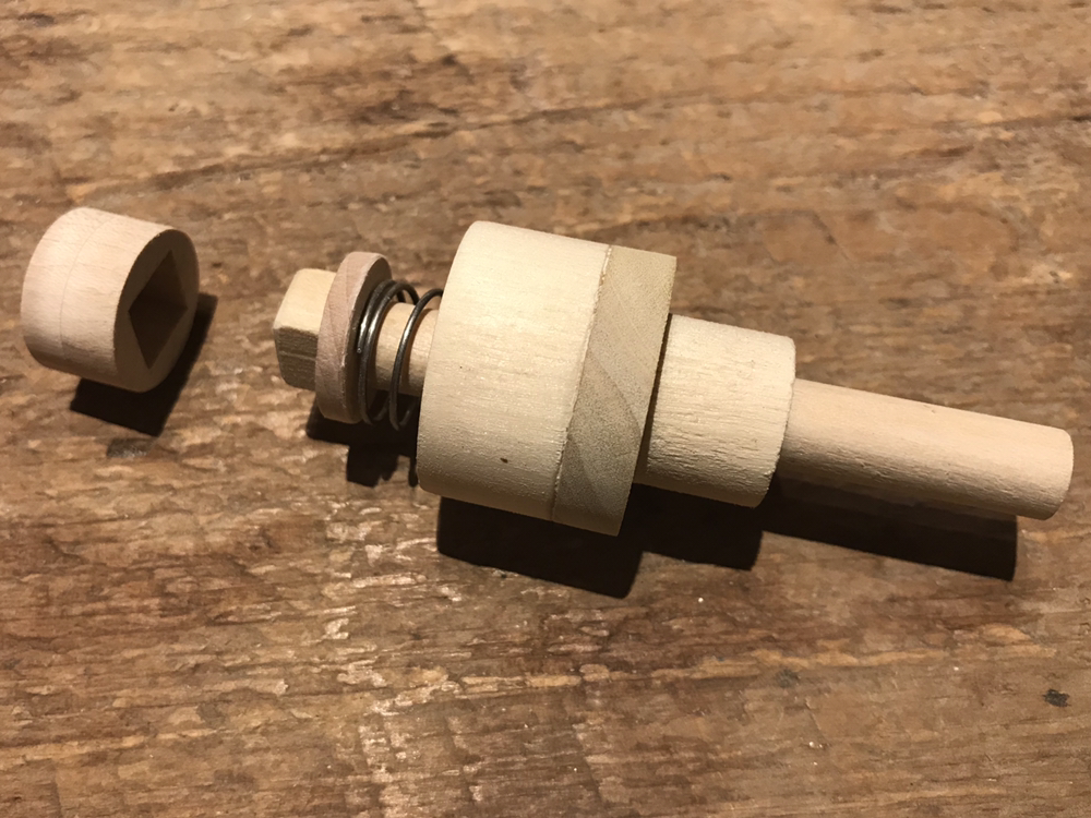
Here is my first attempt at the handle mechanism. The handle is spring loaded. The bushing will be fixed into the hole in the glass urn. The shaft needs to be retractable so the mechanism can be dropped into place, and the shaft can spring back to engage the mechanism in the jar. In the photo the piece on the right will be attached to the mechanism. The square block on the end of the shaft will engage the square hole on the mechanism piece to impart the turning motion. The large bushing around the shaft will protrude through the glass, with a lock ring (not shown), on the outside. A second smaller lock ring glued to the shaft will hold the shaft from protruding beyond the bushing as it is in the photo. No going back now! Undertaking this assembly requires lots of thinking and testing of parts as you go. There is no way to get back to the upper mechanism without cutting our frog apart.
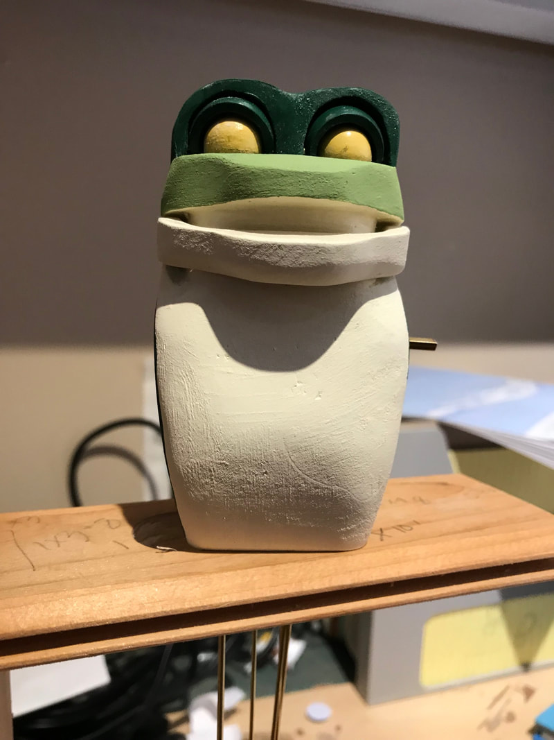
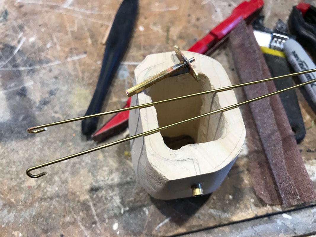
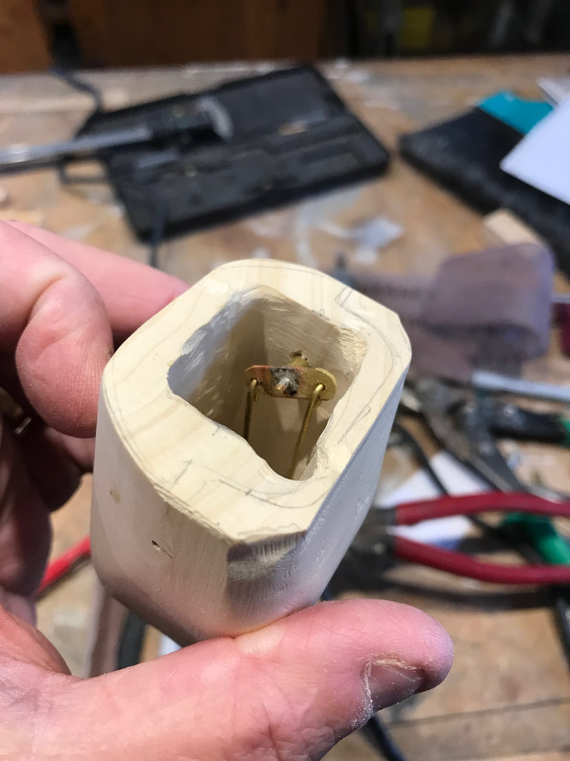
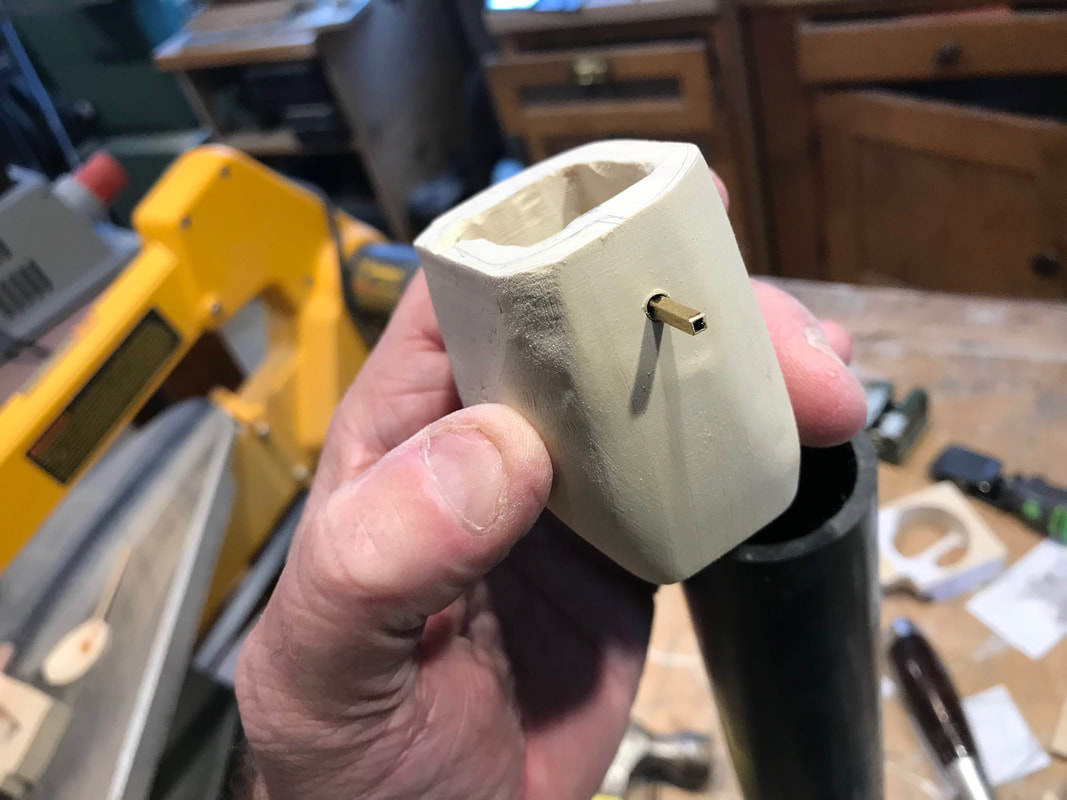
Here is most of Chester the frog glued together in one piece. Since the previous blog entry he has been shaped and sanded and has a rough coat of paint on him. It may be a little early for paint , but I was going to be away from the shop for a while so I took some supplies with me. He needs another sand to get rid of some of those grain marks once the paint hardens and a final paint. His eyeballs don't have pupils in them yet which gives him rather vacant look. He is resting on a little stand, (basically a board with a hole in it) that allows all the brass actuators to hang out the bottom of him so they do not get damaged. This includes: an eyelid open/close actuator (the two rods from the head were soldered together in the space inside the torso to act as one), the eyeball left /right actuator, the mouth open/close actuator, the arm raise/lower actuator and the rod to hang arm counterweights on. His upper legs are made but not attached yet and his lower legs are roughed in. His arms are yet to come. A little more work on my automata frog specimen. This next piece of work may not be obvious to you. My intention is to have this little frog in a glass jar. This means he has to fit down into the jar through the neck, but I do want to have his hand tap on the inside of the jar. This requires that the arm has to be installed after his body is in place. This creates a couple of mechanical issues. His arm has to be correctly positioned on the arm movement shaft so as to have the right range of motion. For this I am putting a square shaft in place which will have a slightly larger square shaft in the arm to slide over it once the frog is installed. I will have to set up the right movement before the mechanism goes into the jar. The second issue will be pushing his arm onto the protruding shaft without pushing the shaft back into the body which will be unaccessible at that time. For this there is a little wooden stop to install at this point of the assembly. Also as I am unsure if any counterweights will be need to balance the arm, or get the right "smack" on the glass, I have made some space for counter weights to be added later if necessary hanging inside the body on a brass rod. The first photo shows the key pieces of the mechanism. There is a small brass strip with three 1/16" diameter holes. A 1/16th" rod, will a flat end protrudes from the centre rear, while the other end is soldered into a small square brass section. The square piece will be where the larger square tube in the arm will fit over. Through the side of the body block is a 5/32" diameter tube that the smaller square section will fit through. It will extend into the inside the body, not like shown in the photo here . It is pushed to the outside so that the arm shaft installed from the inside, can be as long as possible for now. After installing the shaft from the inside, the tube will be pushed in flush with the outside of the body. The two 3/64" rods are for the actuator linkage and possible counterweights. The next photo shows the shaft installed, tube pushed into the body, and the actuator and counterweight rods attached. The tube extends into the body and the end acts as a bushing to keep the mechanism away from the interior body wall and other internal parts. The photo below shows the wooden stop referred to above that prevents the shaft assembly from being pushed inward when install the outer arm. Its odd shape is designed to maximize the gluing surface to the body wall while allowing room for other actuator parts extending down from the head. 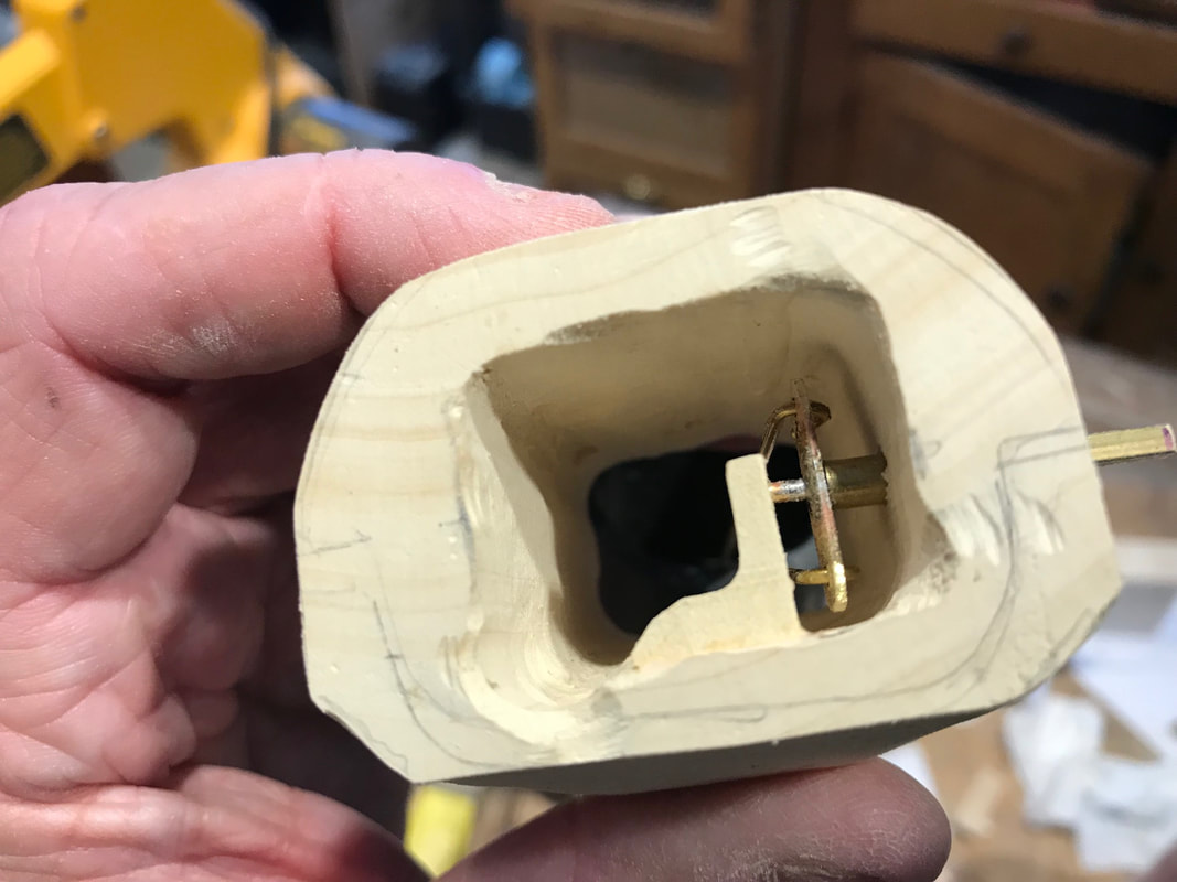 Lastly here is the arm mechanism in place in the roughed in body block. Now it is time to carefully glue the head blocks on and complete the final body shaping when dry.
|
Why Automata?Automata is a creative blend of my life interests , engineering, art and woodworking. Archives
July 2022
Categories
All
|
 RSS Feed