|
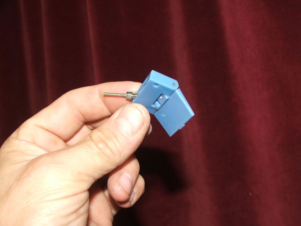
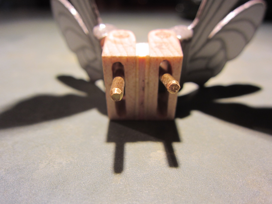
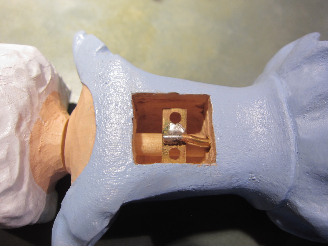
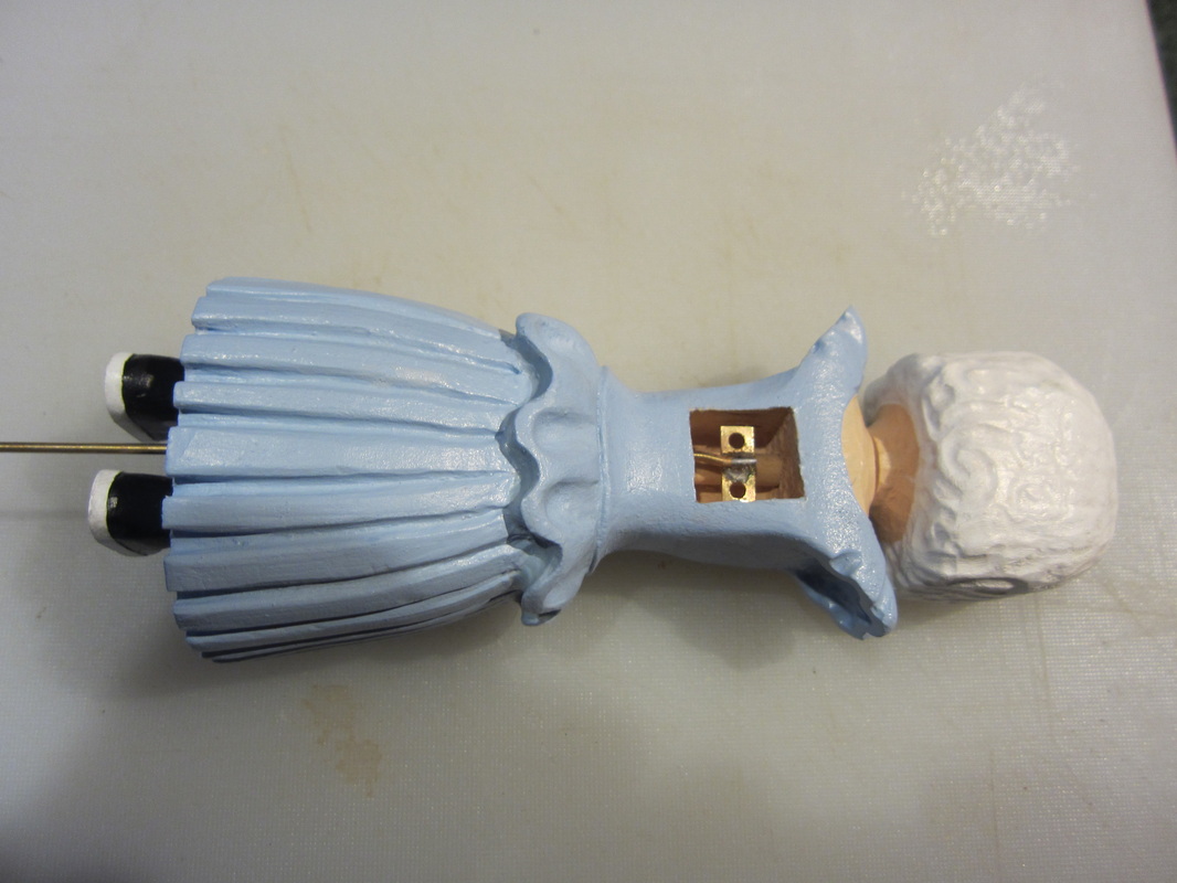
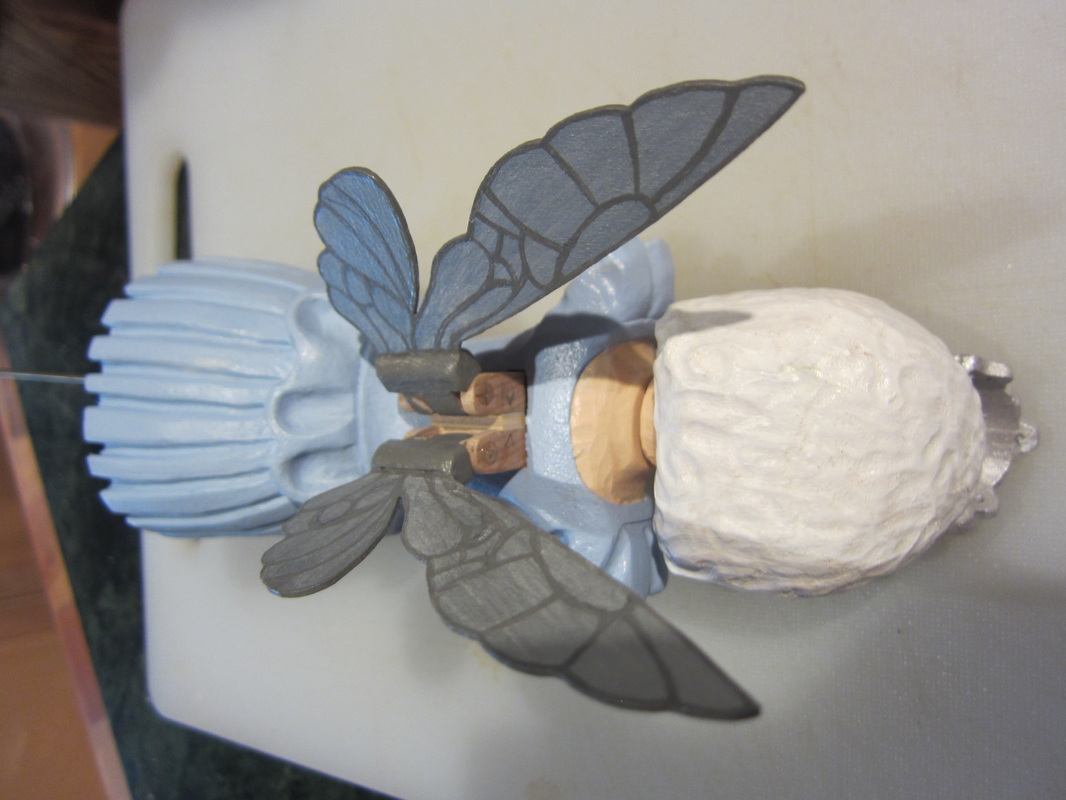
I've had a few questions from web visitors about how to "activate" the fairy wings that I had shown in a previous blog. So I hope this helps. First let's revisit the hinge design. The photo below shows a commercial "Swingee Hinge" used by model aircraft builders used to control ailerons on model aircraft. By pushing the small threaded rod with the nuts on it up and down the flap on the right of the photo waves back and froth. These are available on the internet from hobby suppliers. As I stated in my blog I wanted to stay true to my craft so I built two out of wood and brass, one for each wing of my tooth fairy character. Below is the assembly I made showing two hinges separated by a 1/8" spacer. The spacer merely allows more movement of each wing without interference with the other and to also "straddle" a dowel used to turn the fairy's head (more below). On the rear, the equivalent component to the flap shown above, the two wings are attached. The wings are already painted because it is easier before assembly, but I will do touch-up after it is all put together. Note the brass rods protruding toward the camera. These are the actuator arms. They are not threaded as there is no access to them on assembly to fasten anything. Note also that the ends have being bevelled slightly to make it easier to install the rods through two holes in the activation plate. The first step in assembly is to cut a rectangular hole in the back of the tooth fairy to receive the wing assembly. Test fit the wings into the body. It should be a snug fit as it will be glued in place with adhesive around the outside of the wing assembly. This photo also shows the 1/4" dowel that passes through the cavity that is used to actuate the head on this character. The separation of the activation arms them to pass on either side of the dowel without interference. There is a 1/8" diameter hole drilled up from the base of the character that enters on the centreline of the cavity on the bottom. A 1/16" brass rod is inserted from below to be attached to the activation plate. This rod has a slight offset in the top to ensure it does not interfere with the dowel. The activation plate is made from a flat brass strip with holes drilled on centres that correspond to the the centres of the activation arms. The holes are slightly larger than the diameter of the arms to allow free movement while they move up and down. With some temporary shim material supporting the plate in the cavity I solder it onto the end of the brass rod. Below you can see the rod protruding from the bottom of the tooth fairy's dress. Once assembled, by pulling the rod downward, or letting gravity do its thing, the plate will pull down the arms making the wings flap. If necessary add some weight on the rod lower down. I will use a simple lever riding on a cam to push the wire upward and control wing movement. Now is the time to cut the arms to a length that is not to long and not to short. They should be long enough to not come out of the plate when moved through the full range of movement and not so long as to rub on the back of the cavity. This can also be controlled by how far you insert the assembly into the cavity. Below you can see the wing assembly being pushed into the cavity. Of course patience is required as it usually takes a few attempts to control the wiggling wings and push the pins through the holes in the activation plate. On in, test the motion, mark the depth of insertion, and when ready glue into place. If you intend to use CA glue, use the slow setting stuff and be very careful not to slosh it around and freeze the internal mechanism. Keep moving the wings until you are sure the glue is set. It will not take much to hold the wings in place. Hope this helps! If not send me a note.
Al
0 Comments
Leave a Reply. |
Why Automata?Automata is a creative blend of my life interests , engineering, art and woodworking. Archives
July 2022
Categories
All
|
 RSS Feed