|
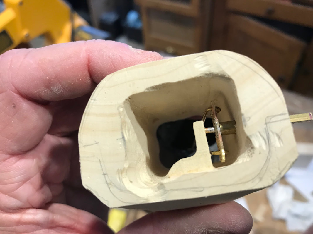
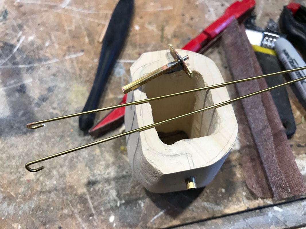
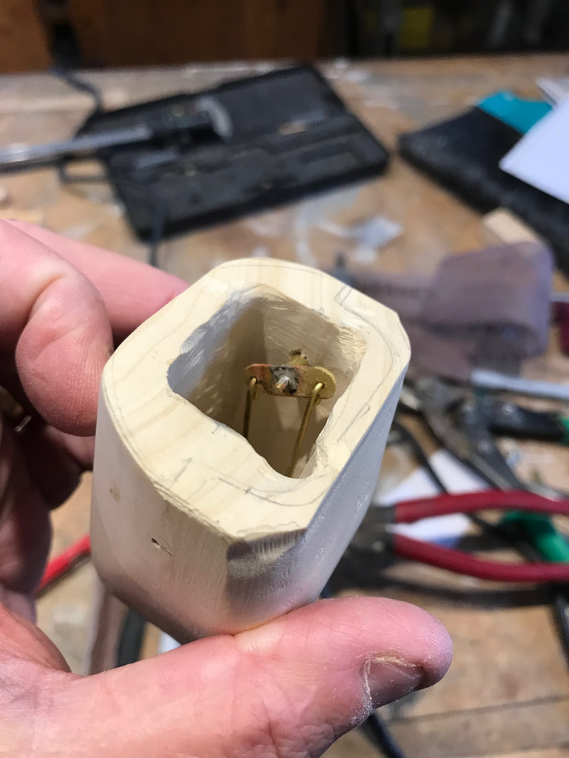
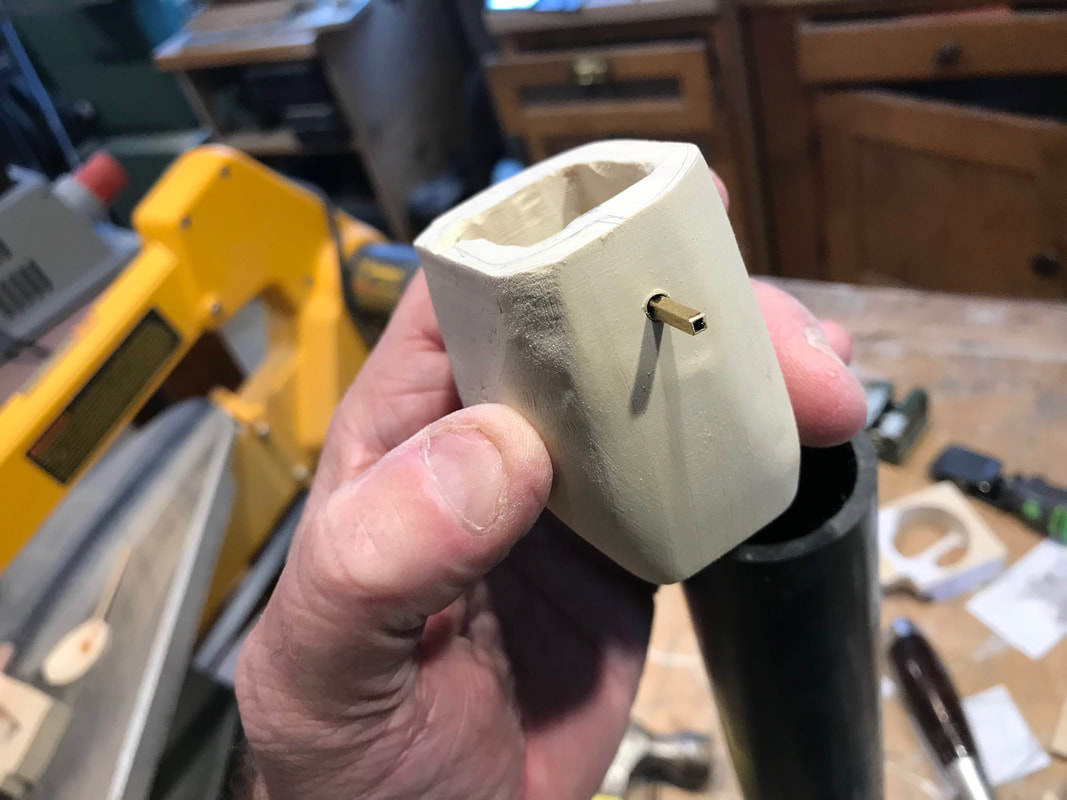
A little more work on my automata frog specimen. This next piece of work may not be obvious to you. My intention is to have this little frog in a glass jar. This means he has to fit down into the jar through the neck, but I do want to have his hand tap on the inside of the jar. This requires that the arm has to be installed after his body is in place. This creates a couple of mechanical issues. His arm has to be correctly positioned on the arm movement shaft so as to have the right range of motion. For this I am putting a square shaft in place which will have a slightly larger square shaft in the arm to slide over it once the frog is installed. I will have to set up the right movement before the mechanism goes into the jar. The second issue will be pushing his arm onto the protruding shaft without pushing the shaft back into the body which will be unaccessible at that time. For this there is a little wooden stop to install at this point of the assembly. Also as I am unsure if any counterweights will be need to balance the arm, or get the right "smack" on the glass, I have made some space for counter weights to be added later if necessary hanging inside the body on a brass rod. The first photo shows the key pieces of the mechanism. There is a small brass strip with three 1/16" diameter holes. A 1/16th" rod, will a flat end protrudes from the centre rear, while the other end is soldered into a small square brass section. The square piece will be where the larger square tube in the arm will fit over. Through the side of the body block is a 5/32" diameter tube that the smaller square section will fit through. It will extend into the inside the body, not like shown in the photo here . It is pushed to the outside so that the arm shaft installed from the inside, can be as long as possible for now. After installing the shaft from the inside, the tube will be pushed in flush with the outside of the body. The two 3/64" rods are for the actuator linkage and possible counterweights. The next photo shows the shaft installed, tube pushed into the body, and the actuator and counterweight rods attached. The tube extends into the body and the end acts as a bushing to keep the mechanism away from the interior body wall and other internal parts. The photo below shows the wooden stop referred to above that prevents the shaft assembly from being pushed inward when install the outer arm. Its odd shape is designed to maximize the gluing surface to the body wall while allowing room for other actuator parts extending down from the head.  Lastly here is the arm mechanism in place in the roughed in body block. Now it is time to carefully glue the head blocks on and complete the final body shaping when dry.
0 Comments
Leave a Reply. |
Why Automata?Automata is a creative blend of my life interests , engineering, art and woodworking. Archives
July 2022
Categories
All
|


 RSS Feed