|
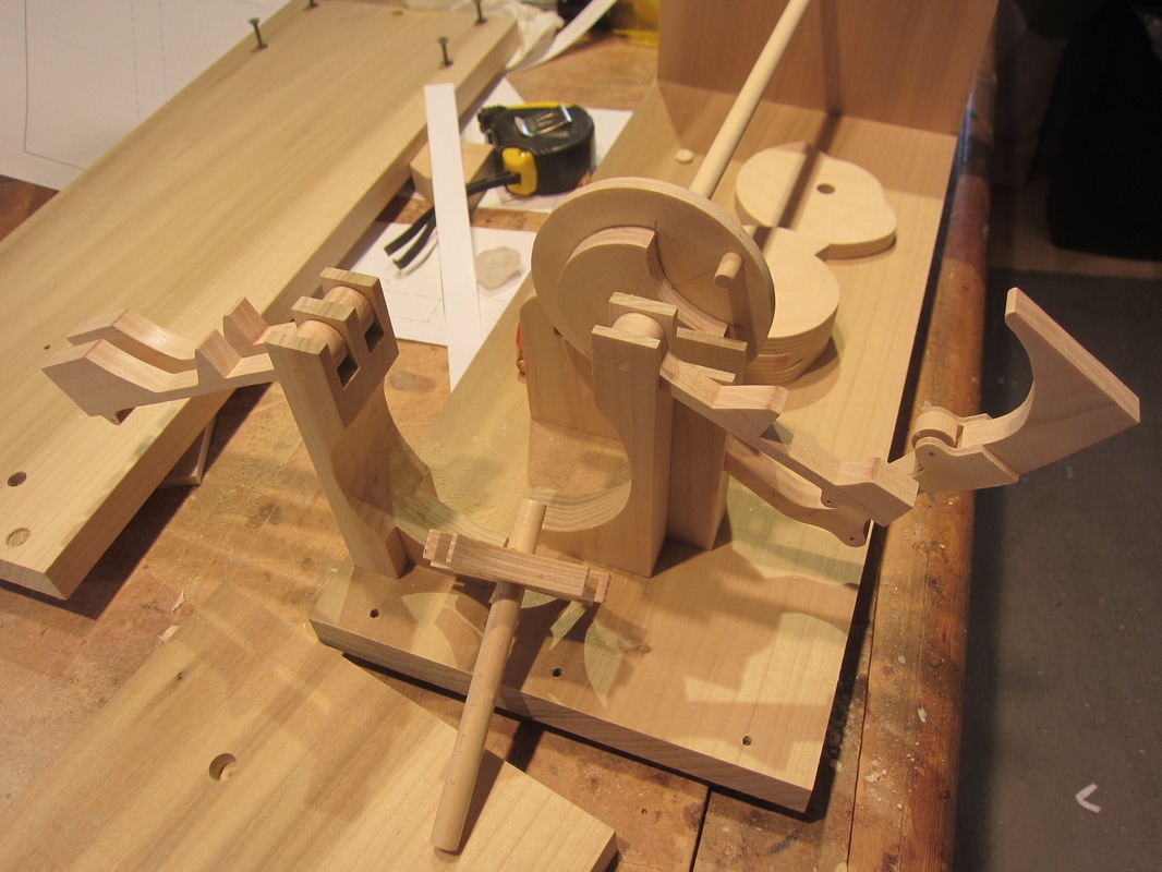
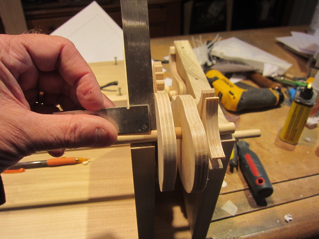
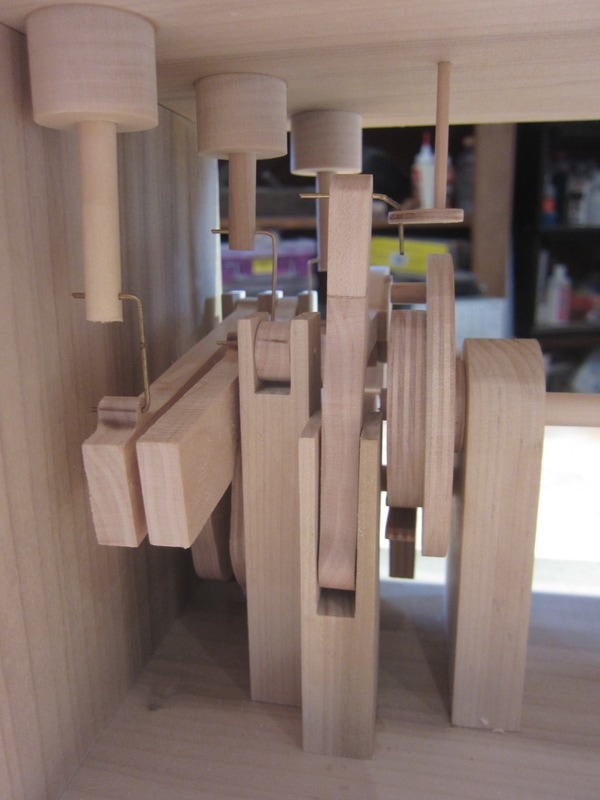
One of the more nerve racking tasks for me in making automata pieces is doing the final glue-up of the cams on the shafts. There are so many ways to slip up! Here's the shorter shaft from my current project being assembled. It is run off the main shaft through a Geneva mechanism. It controls three worms and one baby Sleptin chick. As the little bird peers down a worm hole looking for dinner, other worms around him pop up out of the ground. When he notices and turns to look, the worms quickly dive back down into their holes. The photo below shows the left end of the automata. The left end plate and top plate have been removed for the photograph. You can see the main shaft, no cams install on it yet, in the upper centre. On this side of a main shaft support is the Geneva wheel. The main shaft terminates in this wheel. In the foreground is the short secondary shaft, lying on the base with the Geneva star already installed on the end. I always install the pedestals and followers before fitting the cams. The followers have been "tuned" and mounted to the pedestals which have been glued to the base. The pedestal on the left front has the followers for worms #2 and #3. They will be connected with a 3/64" brass wire to a dowel which will support the worms. The next follower, closest on the right, is the follower for worm #1. The last one is the follower that causes the little Sleptin to turn and look. It has a roller to run on the cam to reduce friction since the cam has a fairly steep profile to overcome to give the desired motion. It also helps because it running away from the hinge point which can be problematic dynamically. So here is the routine I follow in this case. Slide the next cam onto the shaft, The right way of course! Now check it again! Put the shaft in place, and put the left end up. Slide the cam to line up with the follower. Flip the follower over so it sits on the cam and make the final adjustment in cam position. Mark the cam position with a pencil on one side of the cam, in this case the one facing the left end. (toward bottom of photo). Rotate the cam by hand to make sure it does not hit a pedestal, or anything else for that matter! Now disassemble the case and remove the shaft and cams. Using the photo below as a reference, I slide the cam to the left, put a bead of thick CA glue to the right of the line and push the cam into place. Of course before you do this you must know the rotational position of the cam, relative to the others! As the glue is setting rotate it in 90 degree steps and use a small square to make sure it is fitted squarely to the shaft. The photo below shows the assembly sitting on the case for the purpose of taking the photo. I usually do this in my hands. Once the CA has frozen the cam, turn the assembly on end and put some thin CA on the back face of the cam to fill any voids around the shaft. I finish up with a little thick CA glue to build a little fillet. The cam should now have a filet of glue on both sides. Now just keep repeating the as you go along the shaft one cam at a time. SO REMEMBER... 1. Cams on the right way, 2. Align with the followers, 3. Turn to check for interference, 4.Rotated to the correct position, 5. Glued on squarely to shaft! So here's what this area looks like when fitted up in the photo below. The shaft and cams are almost invisible behind all the followers and pedestals. Notice the links to the vertical dowels which have the worms mounted on the other ends. Each of the worm dowels has an extended guide on the bottom of the top plate so they side more smoothly. If the sliding length is to short, the dowels can bind. They will be waxed for lubrication on final fit up. The 1/8" dowel on the right is the one that turns the baby bird. It will have a guide added to the top plate for it as well. The brass wires will also be bent to final shape for locking later.
Some observant readers may have noticed the extension that has been added to the follower that turns the bird between photo 1 and 3. I must have messed up the calculation, since the bird did not rotate as much as I planned . In this case, with enough spaee been the follower and the top plate, I was able to add a 1" extension to the follower to raise the link position. More vertical height translates to more rotation. I hope this was interesting, and answered some questions.
0 Comments
Leave a Reply. |
Why Automata?Automata is a creative blend of my life interests , engineering, art and woodworking. Archives
July 2022
Categories
All
|


 RSS Feed